Experiment #91: op amp metronome – Elenco 130-in-1 Electronics Playground User Manual
Page 110
-110-
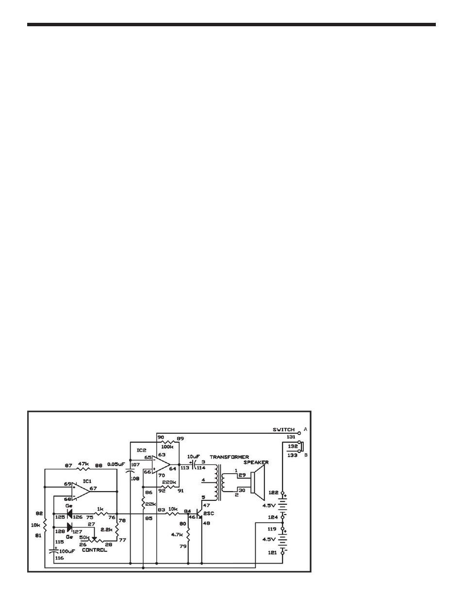
This is the operational amplifier version of the
electronic metronome from Project 3 (“Electronic
Metronome”). Slide the switch to position B, and
connect the wires carefully - this project is more
intricate than most of the others. When you complete
assembling the circuit, set the control to the 12
o’clock position, and slide the switch to position A to
turn on the power. You’ll hear a pip noise from the
speaker at fixed intervals. Now gradually rotate the
control clockwise, and the beats come faster.
Now observe the schematic. IC 1 and IC 2 are used
as astable multivibrators, as in our last experiment.
But you’ll notice that IC 1 uses diodes to generate
short pulses and the control is used to modify the
speed of the pulses. The transistor turns on each
time a pulse is generated, and creates a sound.
Notes:
EXPERIMENT #91: OP AMP METRONOME
Wiring Sequence:
1-29
2-30
3-114
5-47
27-127
28-77
46-80-84
79-70-108-116-48-121
63-131
89-91-113-64
65-90-107
86-92-66
78-76-83-88-67
68-115-125-128
82-87-69
75-126
85-81-119-124
122-132
Schematic
- Upgrade Kit SC100 to SC300 (76 pages)
- Snap Circuits Jr.® Educational 100 Exp. (48 pages)
- Upgrade Kit SC300 to SC500 (64 pages)
- Snap Rover ® (24 pages)
- XP&trade (64 pages)
- Snap Circuits LIGHT ® (84 pages)
- Snap Circuits Extreme® Educational 750 Exp. (88 pages)
- Projects PC1-PC73 (60 pages)
- Electronics 202 (132 pages)
- Snaptricity® (92 pages)
- Upgrade Kit SCROV10 to SCROV50 (48 pages)
- Snap Circuits Green ® (80 pages)
- C Adapter for Snap Circuits® (2 pages)
- Motion Detector Kit (20 pages)
- Digital Roulette Kit (16 pages)
- FM Wireless Microphone Kit (12 pages)
- AM Radio Kit (32 pages)
- AM Radio Kit (36 pages)
- AM/FM Radio Kit (64 pages)
- Circuit Maker Skill Builder 125 (64 pages)
- Circuit Maker Sound Plus 200 (80 pages)
- Understanding Logic Gates (16 pages)
- Understanding Logic Gates and Circuits (42 pages)
- Tumbling Robot (12 pages)
- Solar Energy (16 pages)
- C2D Scope (16 pages)
- 288x Astrolon Telescope with Aluminum Tripod (1 page)
- Simulated Frog Dissection Kit (1 page)
- Talking Galaxy Planetarium with Night Light (1 page)
- Night’n Day® (10 pages)
- Radio Controlled Black Widow (1 page)
- Handheld Microscope (2 pages)
- Water Filtration Kit (8 pages)
- 6-in-1 Solar Kit (18 pages)
- Microscope Set in Carrying Case (1 page)
- Mobile 20 Telescope (1 page)
- Mechanical Drum (20 pages)
- Aerial Screw (20 pages)
- Swing Bridge (20 pages)
- Printing Press (24 pages)
- MultiBarrel Cannon (20 pages)
- Armored Car (24 pages)
- Paddleboat (20 pages)
- SelfPropelled Cart (20 pages)
- Catapult (24 pages)