Experiment #15: light dimmer, Experiment #112: crystal set radio – Elenco 130-in-1 Electronics Playground User Manual
Page 28
-133-
-28-
Ever thought you could use a capacitor to dim a
light? Try this project. After you finish the wiring, set
the switch to A. Then the LED segments will light up
slowly and show an L. Once the LED reaches its
brightest point it will stay on. Move the switch to B
and watch as the L fades away.
Look at the schematic. When the switch is on, the
current flows from the battery to the 100
μF capacitor
to charge. Once the capacitor reaches full charge,
electricity flows to the transistor base and turns it on
gradually, which turns the LED on. Eventually the
capacitor will be completely charged and then the
current flows continuingly to the base of the transistor
and the LED stays on.
When the switch is turned off and you remove the
battery from the circuit, then the capacitor starts to
discharge through the transistor and the LED. The L
dims until the discharge of the 100
μF is finished.
If you want a slower dimmer circuit, all you have to
do is replace the 100
μF capacitor with the 470μF
capacitor. Replace connections 25-116-124 with
connections 25-118-124. Be patient because the
LED does eventually come on.
Go back to project 2 (the police siren) and see if you
can figure out why the siren goes from high to low as
you press and then release the key.
Hint: the 10
μF capacitor charges when you close the
key.
Notes:
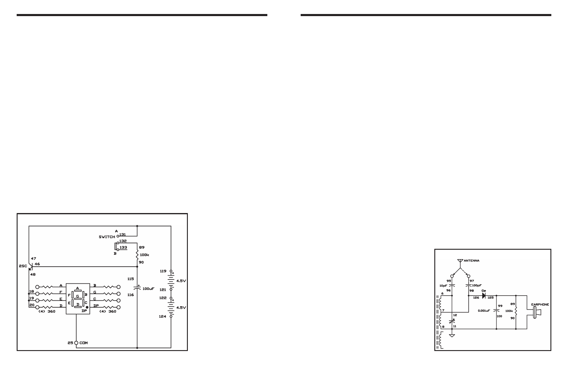
EXPERIMENT #15: LIGHT DIMMER
Wiring Sequence:
o 18-19-20-48
o 25-116-124
o 46-115-90
o 119-47-131
o 89-132
o 121-122
Schematic
The crystal radio is one of the oldest and simplest
radio circuits, which most people in electronics have
experimented with. In the days before vacuum tubes
or transistors, people used crystal circuit sets to pick
up radio signals.
Since the crystal radio signals are very weak, you’ll
use a ceramic type earphone to pick up the sounds.
These earphones reproduce these sounds well
because it is and requires little current.
Necessary for receiving distant stations is a good
antenna and earth ground connection is, but you can
hear local stations using almost anything as an
antenna. A long piece of wire (like the green wire in
your kit) makes an acceptable antenna in most cases.
When “earth ground” is referenced it means just that;
you connect the wire to the ground. You can easy
make an earth ground connection by connecting a
wire to a metal cold water pipe. If you can also drive
a metal stake into the ground and connect the wire to
the stake.
Construct the circuit according to the wiring sequence
to use your crystal diode radio. The circuit has two
antenna connections for either short or long antennas,
but only use one at time. Connect short antennas, 50
feet or less on terminal 95 and longer antennas on
terminal 97. Try out each connection and use the one
that results in the best reception.
Tank circuit is the part of the radio circuit that includes
the antenna coil and the tuning capacitor is called.
When a coil and the tuning capacitor are connected
in parallel, the circuit resonates only at one frequency.
So the circuit picks up only the frequency that
generates the tank circuit to resonate. The tuning
capacitor alters its capacitance as you rotate it. When
the capacitance changes the resonating frequency of
the circuit changes. Thus, you can tune in various
stations by rotating the tuning capacitor. Without this
selectivity, you might hear several stations mixed
together (or only a lot of noise).
The tank circuit receives high-frequency RF (radio
frequency) signals. The broadcast station uses sound
signals to control the amplitude (strength) of the RF
signals - that is, the height of the RF wave varies as
the sound varies. The diode and the 0.001
μF
capacitor detect the changes in the RF amplitude and
convert it back to audio signals. The conversion of
amplitude modulation signal into audio signal is called
detection or demodulation.
Notes:
EXPERIMENT #112: CRYSTAL SET RADIO
Schematic
Wiring Sequence:
o 6-12-96
o 7-98-126
o 8-11-90-100-EARPHONE
o 89-99-125-EARPHONE
o 95-ANT or (97-ANT)