Experiment #54: a one-shot ttl, Experiment #71: changing input voltage – Elenco 130-in-1 Electronics Playground User Manual
Page 71
-71-
What does “one-shot” mean to you?
Turn the switch to A, and see what happens to LED
1 when you press the key once at a time. Try holding
the key down for different periods while watching
LED 1. Does LED 1 stay on the same length of time
or does it change?
Regardless of the length of the input, you see that a
one-shot multivibrator has an output for a certain
length of time. (It “fires one shot.”) This means that it
can be applied in many circuits as a timer. This circuit
is also called a monostable multivibrator.
Notes:
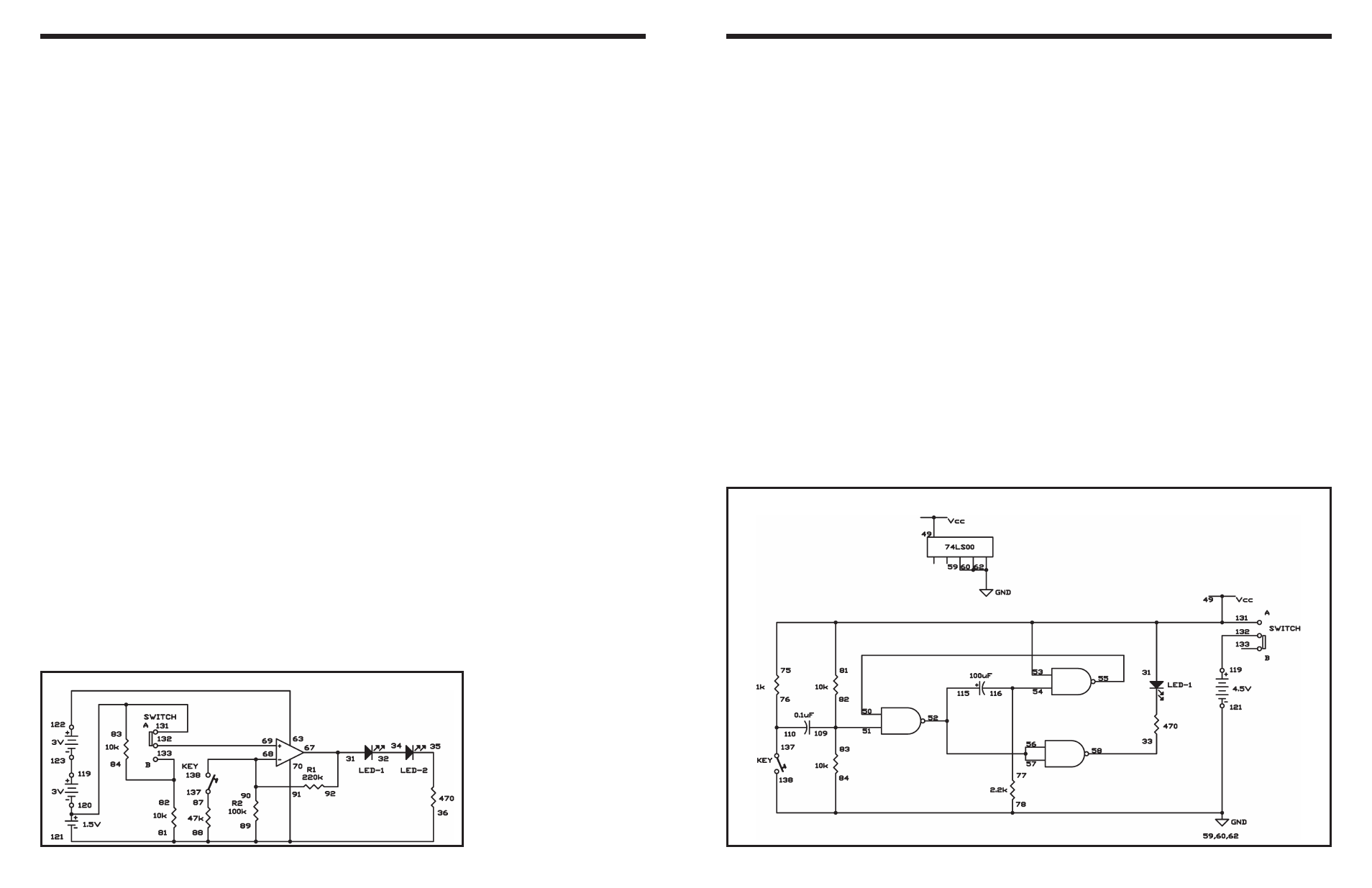
EXPERIMENT #54: A ONE-SHOT TTL
Wiring Sequence:
o 81-75-49-53-31-131
o 33-58
o 50-55
o 51-82-83-109
o 52-56-57-115
o 54-77-116
o 59-60-62-78-84-138-121
o 76-110-137
o 119-132
Schematic
After you finish the wiring, set the switch to position B.
LEDs 1 and 2 indicate the output voltage of the
operational amplifier IC. An LED lights if it is
connected to 1.5V or higher. In this experiment, we
connect the two LEDs in series, so they only light
when connected with about 3V. When they are off,
the output voltage of the operational amplifier must
be less than 3V.
View the schematic diagram. With the switch at
position B, the 1.5V battery voltage is connected to
two 10k
Ω resistors, with the positive terminal of the
operational amplifier connected between the
resistors. These two 10k
Ω resistors divide the 1.5V
supply voltage in half. This signifies the positive input
terminal receives an input voltage of only 0.75V.
To total the output voltage of the operational amplifier
you multiply its input voltage by the amplification
factor (R1/R2) + 1. So, the output voltage is 0.75V x
((220k
Ω / 100kΩ) + 1) = 2.4V.
Slide the switch position A. This eliminates the 10k
Ω
resistors from the circuit, so the amplifier’s positive
input terminal receives the full 1.5V input voltage.
Using the above equation, you can see that the
output voltage of the operational amplifier is now
1.5V x ((220k
Ω / 100kΩ) +1) = 4.8V. Because the
voltage supplied to them is more than 3V, the LEDs
light dimly.
Let’s alter the amplification factor. Slide the switch to
position B again and press the key. This adds the
47k
Ω resistor to the 100kΩ resistor in parallel,
making total resistance of R2 about 32k
Ω. Now the
output voltage is 0.75V x ((220k
Ω / 32kΩ) +1) = 5.9V,
enough to light the LEDs brightly.
Now slide the switch to position A again (to connect
1.5V to the amplifier’s positive (+) input terminal), and
press the key. The LEDs light brightly. Calculating the
output voltage gives 1.5V x ((220k
Ω / 32kΩ) +1) =
11.8V. However, the actual output voltage will be
limited by the available battery voltage, which is 1.5V
+ 3.0V + 3.0V = 7.5V.
Notes:
EXPERIMENT #71: CHANGING INPUT VOLTAGE
Wiring Sequence:
o 31-67-92
o 32-34
o 81-89-88-70-36-121
o 63-122
o 68-90-91-138
o 69-132
o 82-84-133
o 83-131-120
o 87-137
o 119-124
-90-
Schematic