Experiment #28: “toggle flip-flop” transistor, Experiment #98: reset circuit – Elenco 130-in-1 Electronics Playground User Manual
Page 43
-118-
-43-
Now it is time to step into the world of digital circuits
and learn some basics. A circuit that acts as a switch
to turn different components off and on is a digital
circuit. In this section you will be dealing with diode-
transistor logic (DTL) circuits- these are circuits that
use diodes and transistors to turn the power on and
off.
It doesn’t usually matter how much voltage is applied
to a digital circuit; what matters is whether the circuit
is off (no voltage present) or on (presence of
voltage). When a circuit is off we describe it as logic
low or use the number 0. When a circuit is turned on
we say logic high or use the number 1.
A switch that turns circuits on and off is a toggle
switch. In this experiment we will use the flip-flop
circuit to work as a toggle switch. In this project,
unlike others that you will be doing later, the circuit
does not change until you tell it to.
Once you have completed the wiring, set the switch
to A. The lower part of the LED lights up. Press the
key now. The upper section lights up while the lower
section shuts down. Every time you press the key the
LED sections will change, thus a flip and a flop.
When a transistor is on and the other transistor is off,
it will stay either on or off until you tell it to change.
We can easily say that a flip-flop circuit remembers.
Once you put a circuit into a certain setting, it will stay
that way until you tell it to change. Controlled by a
single toggle signal, flip-flops can remember many
things. This is also why computers can remember so
many things.
Notes:
EXPERIMENT #28: “TOGGLE FLIP-FLOP” TRANSISTOR
Wiring Sequence:
o 84-108-44-17
o 81-106-41-20
o 25-124-137
o 40-107-83
o 42-110-72
o 45-130
o 43-105-82
o 71-75-111-131-129
o 76-109-112-138
o 119-132
o 121-122
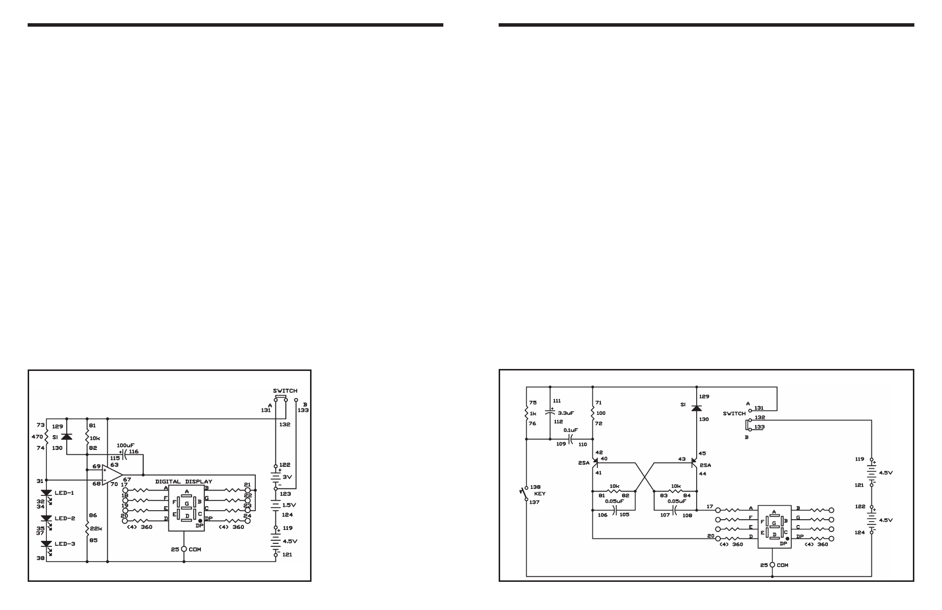
Schematic
Do you know what a reset circuit does? It activates
other circuits and detects any power fluctuations in
order to prevent malfunctions. In this experiment, we
change the supply voltage to the circuit with the
switch. The power to the display portion of the circuit
is on, or logic high, when the switch is set to position
A; it is off when the switch is at position B. When the
circuit has been reset the LED display shows 1.
Let’s start experimenting. First, finish the wiring and
set the switch to position B. Now, with the switch set
to B, the power reset circuit operates under 6V, and
the three LEDs light dimly. The LED display is off,
meaning that the display circuit is not activated.
Now set the switch to position A. You can see the
three LEDs light brightly because the supply voltage
has been modified to 9V. For a moment, the LED
display still shows no change, indicating that the
circuit is being reset. After a short interval, the LED
displays 1 to show that the circuit has finished
resetting and now it is stabilized.
Set the switch to position B to switch the power back
to 6V. You will observe the 1 on the LED disappear,
because now the display circuit is off.
Study the schematic to understand how the circuit
works. The operational amplifier is a comparator. The
3 LEDs are connected together to make a reference
voltage of about 5.4V for the negative (–) terminal.
With the switch in position B, the positive (+) terminal
receives about 4.1V, so the comparator does not
allow the display to light. With the switch in position
A, the battery voltage is increased to 9V, and the
100
μF capacitor gradually causes the comparator’s
positive (+) terminal voltage to increase to about 6V.
When this voltage exceeds the reference voltage of
5.4V, the LED display lights 1.
When you set the switch to B, the voltage at the
amplifier’s positive (+) terminal discharges through
the diode, so the voltage is reduced to 4.1V.
Although this circuit seems very simple (consisting
of only one operational amplifier), it is very complex
and important for later use.
Notes:
EXPERIMENT #98: RESET CIRCUIT
Wiring Sequence:
o 21-23-67-116
o 85-70-38-25-121
o 31-68-74
o 32-34
o 35-37
o 73-81-63-129-132
o 86-82-69-115-130
o 119-124
o 122-131
o 123-133
Schematic