Reznor RXH (Outdoor PreevA) Unit Installation Manual User Manual
Page 7
Form I-RDH/REH/RHH/RXH (12-14), P/N 215210 R14, Page 7
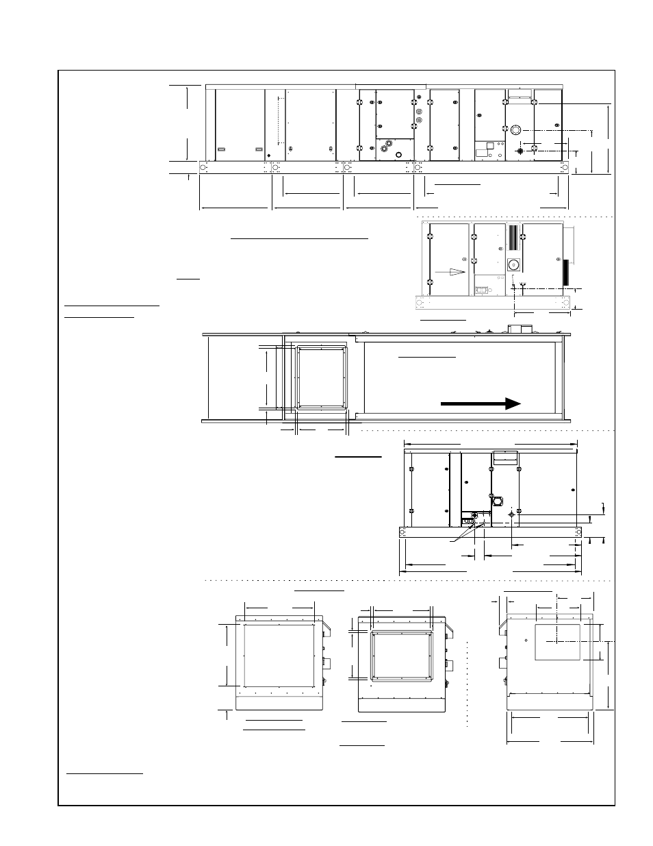
FIGURE 2 - Dimensions - Models RDH, REH, RHH, and RXH (no heat model only) with Horizontal
Discharge (no Downturn Plenum)
Front View
D
(
inside curb cap
)
B
(base width)
K
L
cL
cL
N
M
3-1/16
77 mm
RDH/
RHH
only
Rear View with Optional
Inlet Duct Flange
Rear View of
Basic Cabinet
(If basic unit only, optional
outside air hood is
installed here; see page 25.)
F
G
J
H
9-1/16
230mm
Inlet
Air
Opening
(JxH)
Inlet Air
with
Duct
Flange
3/4(19 mm)
Duct Flange
Rear View with Optional
Evap Cooler, see page 32.
Rear Views -(RDH shown;
dimensionsapply to allModels)
Side View - RDH
A1, A2
C
(inside curb cap length)
C1, C2
C3, C4
A3, A4
A
(length of base rail)
Optional
Mixing
Box
Optional
Cooling
Module
with or
w/o
Reheat
Blower Cabinet & Heat Section
E
Mounted
Height
cL
cL
cL
17-15/16
455mm
P
R
9-1/4
235mm
6-1/4
159mm
Vent
Combustion
Air*
Gas Connnection
Optional
Evap
Cooling
Module
A5, A6
Bottom View with Optional
Cooling Coil Module and Mixing Box
(no downturn plenum) -
RDH illustrated; applies to all models
Airflow
F
G
3/4(19 mm)
Duct Flange
Return
Air with
Optional
Mixing
Box only
Side View - REH
Airflow
X
Side View of Optional Modules
Side View Dimensions A, C, and E are the same for
Models RDH, REH, RXH (subject to option availability).
Model RHH side dimensions are longer.
NOTE: Side view of no heat Model RXH is not
illustrated but includes the blower section and the
heat section cabinets less the heating components.
Dimensions here apply to no heat RXH only. For
RXH with hot water heat, see page 38.
Blower
Electrical
Electric
Heat
Section
Electrical
Supply Inlet
8-1/4
(210)
Duct
Flange
- Std on
REH w/o
downturn;
Optional
on RDH,
RHH, RXH
Heat Section
Access Panel
Blower and
Motor
Access
Panel
Control
Access
Panel
Field Connection
Access Panel
81-5/8 (2073)
Side View -
High Efficiency
Model RHH
NOTE: Model RHH
must be mounted on a
roof curb. The area
within the curb under
the unit must be open.
11-23/32
(297)
7-1/2
(191)
35-5/8 (905)
Electrical
Connections
Gas Connection
48-1/4 (1226)
3-27/32 (98)
79-15/16 (2030) - Inside Curb Cap
86-1/2 (2197)
NOTE: An optional
evaporative cooling
module (Option ECC)
is always first and
extends beyond the
roof curb. It has no
affect on inside curb
length, Dimension
C.
Other Dimensions:
All Configurations with a Downturn Plenum (Option AQ), FIGURE 4, page 9.
Outside Air Hood (Option AS2), FIGURE 19A, page 25.
Dimensions Specific
to each Module:
Mixing Box (MXB),
FIGURE 22, page
27.
Evaporative
Cooling Module
(ECC),
FIGURE
25, page 32.
Chilled Water
Cooling Coil
Cabinet (AU6),
FIGURE 31, page
35.
DX Cooling Coil
Cabinet (AU5),
FIGURE 32A,
page 36.
DX Cooling Coil
Cabinet w/Reheat
(AU7),
FIGURE
32B, page 36.
Hot Water Heat
Module for RXH,
FIGURE 36A page
39.
RDH Gas Heat,
FIGURE 2 top of
page &
FIGURES
14A&B, page 22.
REH Electric Heat,
Side View above.
RHH High
Efficiency Model,
Side View center
right and
FIGURE
15, page 23,
for heat section
drain connection
location.