9 blowers, belts, and drives - rdh, reh, rhh, rxh, 0 mechanical (cont’d) – Reznor RXH (Outdoor PreevA) Unit Installation Manual User Manual
Page 42
Form I-RDH/REH/RHH/RXH (12-14), Page 42
6.9 Blowers, Belts,
and Drives - RDH,
REH, RHH, RXH
3/4 (19mm)
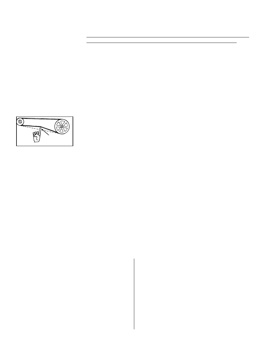
FIGURE 39 - Check Belt
Tension
6.9.1 Belts and Belt Tension
Check belt tension. Proper belt tension is important to the long life of the belt and
motor. A loose belt will cause wear and slippage. Too much tension will cause exces-
sive motor and blower bearing wear. Adjust the belt tension by turning the adjusting
screw on the motor base until the belt can be depressed 3/4” (19mm). (See
FIGURE
39.) After correct tension is achieved, re-tighten the locknut on the adjustment screw.
Be sure that the belt is aligned in pulleys.
Linked Belts - If the belt needs tightening, the recommended method of tightening the
belt length is to count the number of links and remove one link for every 24. (A link is
made up of two joining sections of belt. For easier removal of links, turn the belt inside
out. But be sure to turn it back before installing. If belt is removed or replaced, be sure
to align directional arrows on the belt to the proper drive rotation.) The belt tension
should be checked after the first 24 hours of running at full load and at regular mainte-
nance inspections. Be sure that the belt is aligned in the pulleys.
Solid Belts - Adjust the belt tension by turning the adjusting screw on the motor base
until the belt can be depressed 3/4” (19mm). (See
FIGURE 39.) After correct tension
is achieved, re-tighten the locknut on the adjustment screw. Be sure that the belt is
aligned in the pulleys.
6.0 Mechanical
(cont’d)
through the hole and secure the bulb to the clip in the holder. Slide the holder into
the ductwork. Using four field-supplied No. 6 sheetmetal screws, attach the box
portion of the holder to the ductwork. Attach the cover on the box.
Sensor with Wire (Options AG15, AG16, AG58, AG61, AG62, DG5, DG6, D12B,
D12C, D12D, D12E, and D12G and field-supplied sensor for Option AG40) - Push
the element into the clip in the holder. Determine where the sensor wire should
enter the box and remove the knockout. Slide the holder into the ductwork. Using
four field-supplied No. 6 sheetmetal screws, attach the box portion of the holder
to the ductwork. Attach a field-supplied cable connector to the box, connect the
sensor wire, and attach the box cover.
If sensor is digital, follow the wiring instructions above. To test the accuracy of the
sensor, measure the ohms. Refer to
TABLE 26B (left) to determine the correspond-
ing temperature.
The blower speed may be adjusted to achieve the desired outlet temperature, as long
as the adjustment is within the temperature rise and the static pressure limits shown
on the furnace rating plate. Motors are factory set between maximum and minimum
blower speeds.
If the duct resistance is low, the blower may deliver too high an air volume. If the resis-
tance is very low, the blower may deliver excess air volume to overload the motor,
causing the overload protector to cycle the motor. Reducing the blower speed will cor-
rect these conditions. If ductwork is added to an installation, it may be necessary to
increase the blower speed. Decreasing blower speed will increase outlet temperature;
increasing blower speed will decrease outlet temperature.
6.9.2 Adjusting Blower
Speed
At final adjustment, amperes should not exceed motor nameplate amp rating. The installation must be adjusted
to obtain a temperature rise within the range specified on the furnace rating plate.
The belt drive on these units is equipped with an adjust-
able pulley which permits adjustment of the blower speed.
Follow these instructions to adjust the blower speed.
1. Turn off the gas (RDH & RHH) and the electric power
(RDH, REH, RHH, RXH).
2. Loosen belt tension and remove the belt.
3. Loosen the set screw on the side of the pulley away
from the motor.
4. To increase the blower speed, turn the adjustable
half of the pulley inward.
To decrease the blower
speed, turn the adjustable half of the pulley outward.
One turn of the pulley will change the speed 8-10%.
5. Tighten the set screw on the flat portion of the pulley
shaft.
6. Replace the belt and adjust the belt tension. Adjust
tension by turning the adjusting screw on the motor
base until the belt can be depressed 3/4”. (See
FIGURE 39.) Re-tighten the lock nut on the adjusting
screw. Be sure that the belts are aligned in the pulley
grooves properly and are not angled from pulley to
pulley.
7. Turn on the power (RDH, REH, RHH, RXH)) and the
gas (RDH & RHH). Set the control to call for heat.
8. Check the motor amps with an ammeter. The
maximum motor amp rating on the motor nameplate
must not be exceeded.
When service is complete, check for proper operation.
6.8 Unit Discharge -
RDH, REH, RHH,
and RXH
6.8.5 Discharge Air
Sensor for Makeup Air
Application (cont’d)