0 mechanical (cont’d) – Reznor RXH (Outdoor PreevA) Unit Installation Manual User Manual
Page 40
Form I-RDH/REH/RHH/RXH (12-14), Page 40
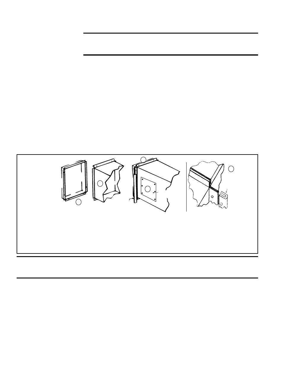
FIGURE 37 -
Connecting
Discharge
Ductwork
(1) If the heater has an optional duct flange, the flanges turn out as shown. (2) Shape duct connection as shown
with “U” on top and bottom and “L” on sides.
(3) Provide for sealed access panel in the ductwork. This opening must
be accessible when the furnace is in service and should be large enough to view smoke or reflected light, to detect
the presence of leaks in the heating equipment, and to check for hot spots on the heat exchanger due to poor air
distribution or lack of sufficient air (cfm). The cover for the opening must be attached in such a manner as to prevent
leakage.
(4) Slide “U” channels over top and bottom flanges on the heater. (5) Form field-supplied “U” channels over
side connections to seal. Drill and lock with sheetmetal screws.
Heater
Duct
Access Panel
in Duct
1
2
3
4
U Channel
(see englared
view on the right)
Furnace
Duct
U Channel
of Light
Gauge Metal
5
CAUTION: Joint where supply air duct attaches to the furnace must be sealed securely to
prevent air leakage. Leakage can cause poor combustion, shorten heat exchanger life, and
cause poor performance. See Hazard levels, page 2.
All gas or electric control options for makeup air (except AG40) include a discharge
air sensor that requires field installation in the discharge duct. (Sensor is field-supplied
with Option AG 40.)
Options AG3, AG15, AG16, AG58, AG60, AG61 and AG62 are analog controls. Options
AG3 and AG60 have a unit mounted ductstat with a capillary sensor that will fit in the
holder in
FIGURE 38. Options AG16, AG58, AG60, AG61 and AG62 include sensors
that require duct mounting using the holder in
FIGURE 38 and field wiring. Follow the
instructions below to attach the holder and the sensor.
Sensors in Options DG5, DG6, D12B, D12C, D12D, D12E, and D12G are digital and
require duct mounting using the holder in
FIGURE 38 and field wiring. Digital control
inputs are low-current, resistance-based signals. For optimum temperature control
performance the analog and digital inputs (zone sensors, discharge air sensors, etc.)
6.8.5 Discharge Air
Sensor for Makeup Air
Application
6.0 Mechanical
(cont’d)
6.8.4 Requirements
and Recommendations
for Connecting and
Installing Ductwork
(cont’d)
Conditioning Contractors Association (www.acca.org), 2800 Shirlington Road, Suite
300, Arlington, VA 22206. A manual covering duct sizing in detail may be purchased
directly from them.
CAUTION: An external duct system static pressure not within the
limits shown on the rating plate, or improper motor pulley or belt
adjustment, may overload the motor. See Hazard Levels, page 2.
• Removable Panel (See FIGURE 37.) - The ductwork should have a removable
access panel. This opening must be accessible when the furnace is in service and
should be large enough to view smoke or reflected light, to detect the presence of
leaks in the heating equipment, and to check for hot spots on the heat exchanger
due to poor air distribution or lack of sufficient air (cfm). The cover for the opening
must be attached in such a manner as to prevent leakage.
• Horizontal Discharge Duct Length - A minimum horizontal duct run of 24”
(610mm) is recommended before turns or branches are made in the duct system
to reduce losses at the furnace outlet.
• Discharge Air Horizontal Connection (See FIGURE 37.) - The seal between the
heater and the duct must be mechanical. Duct connection should be made with
“U” type flanges on the top and bottom of the connecting duct. Slide the duct over
the flanges of the heater giving an airtight fit. Provide “U” type channels for the
side flanges to ensure tight joints. Fasten “U” channels with sheetmetal screws.
• Bottom Duct Connection - To minimize sound and vibration transmission, use
a flexible duct connection. Duct must be attached and sealed to provide air tight
connection.
6.8 Unit Discharge -
RDH, REH, RHH,
and RXH