0 mechanical (cont’d), Instructions for high altitude derate – Reznor RXH (Outdoor PreevA) Unit Installation Manual User Manual
Page 20
Form I-RDH/REH/RHH/RXH (12-14), Page 20
Derate by Valve Outlet
Pressure Adjustment
if needed for High
Altitude Operation
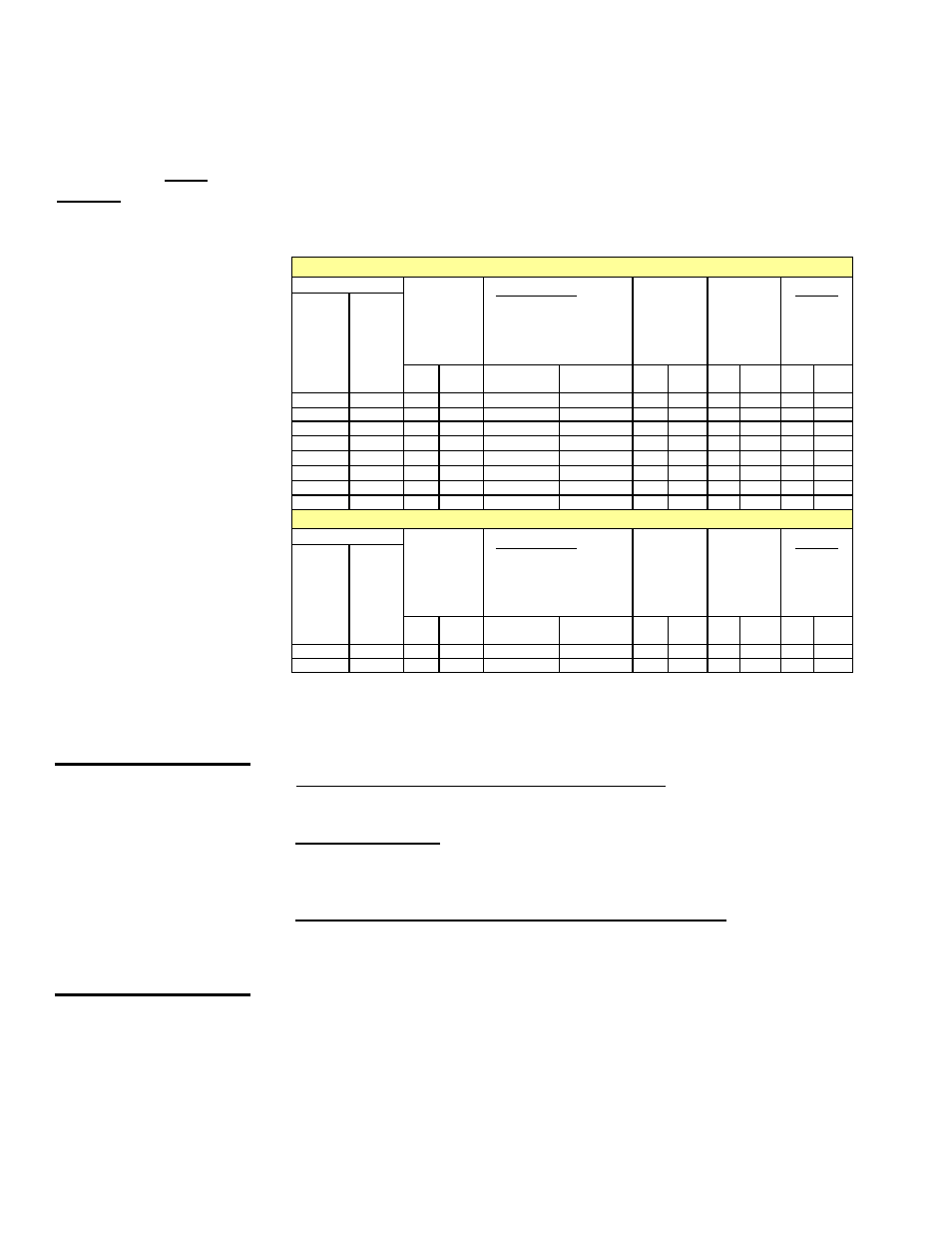
TABLE 11 - Valve Outlet
Pressure Settings by
Elevation, Gas Control
Option, and Type of
Gas for Models RDH
and RHH
If the elevation on the rating plate does not match the elevation of the installation site,
follow these instructions to adjust the valve.
Instructions for High Altitude Derate
1. Refer to TABLE 11 and determine the required valve outlet pressure(s) for the
elevation where the heater will be operating. If unsure of the elevation, contact the
local gas supplier. If unsure of the type of gas control, check the option list on the
unit wiring diagram.
CAUTION: DO NOT
bottom out the gas
valve regulator
adjusting screw.
This can result in
unregulated manifold
pressure causing
excess overfire and
heat exchanger
failure.
2. Locate the 1/8” outlet pressure tap on the valve (FIGURE 11A, page 17). Turn the
or switch knob on the top of the valve to “OFF”. Connect a manometer to the 1/8”
outlet pressure tap in the valve. Use a water column manometer that is readable
to the nearest tenth of an inch. When making the adjustment, turn the adjustment
screw IN (clockwise) to increase pressure or OUT (counterclockwise) to decrease.
3. Single-Stage and Two-Stage High Fire Adjustment - Turn the switch or knob on
the top of the valve to “ON”. Remove the cap from the pressure adjusting screw
and adjust the outlet pressure to the full rate pressure selected from
TABLE 11.
Two Stage Low Fire - Disconnect the wire from the “HI” terminal on the gas valve
and check low fire pressure. To adjust, turn the low pressure regulator screw to
achieve the “2-Stage Low Fire” pressure listed
for the applicable gas control
(TABLE 11). Re-connect the wire to the gas valve.
Electronic Modulation Options AG40, DG2, DG6, and D12B - The electronic
modulation valve itself has no high fire adjustment. The only adjustment on the
modulation valve is the low-pressure bypass setting which is factory set and does
not require field adjustment for high altitude operation.
However, if the elevation on the rating plate does not match the elevation of the
installation, a full rate adjustment is required at the outlet of the combination valve.
To make the full rate adjustment, adjust the outlet pressure of the combination gas
valve when the modulating valve is fully open (there must be a minimum of a 20
VDC signal at the electronic modulating valve to ensure that it is fully open). Set
the outlet pressure of the combination valve to the pressure shown in
TABLE 11.
4. Turn up the thermostat. Cycle the burner once or twice to properly seat the
adjustment spring in the valve. Re-check the pressure(s). When the outlet
pressure(s) is right for the installation, remove the manometer and replace the
cap. Check for a leak at the pressure tap fitting.
6.0 Mechanical
(cont’d)
6.1 Gas Piping and Pressures - Models RDH and RHH (cont’d)
6.1.3 High Altitude Operation - Gas-Fired Model RDH or RHH being
installed above 2000 ft (610M) (cont’d)
Outlet Pressure Settings (inches w.c.) by Altitude for Installation in the UNITED STATES
Altitude
Full Rate Outlet
Pressure (Single-
Stage & 2-Stage
High Fire) - Applies
to Options AG1,
AG2, AG3, AG15,
AG16, AG60, AG61,
AG62, DG1, DG5,
D12C, D12F
Full Rate Outlet Pressure with
Electronic Modulation - Applies to
Options AG8, AG9, AG9H, AG40, DG2,
DG6, and D12B (measured at the outlet
pressure tap just behind the orifice
adapter when there is a minimum
of a 20VDC signal at the electronic
modulating valve)
NOTE: Options do not apply to SHH.
2-Stage Low-Fire
Outlet Pressure -
Applies to Options
AG2, AG3, AG15,
and AG16
2-Stage Low-Fire
Outlet Pressure
with Venter
Motor Controller
- Applies to
Options AG60,
AG61, AG62, DG1,
DG5, D12C
Factory-Set
Bypass Pressure
with Electronic
Modulation
- Applies to
Options AG40,
DG2, DG6, D12B
FEET
METERS
Natural
Gas
Propane
Natural
Gas
Propane
Natural
Gas
Propane Natural
Gas
Propane Natural
Gas
Propane
0 - 2000
0 - 610
3.5
10.0
3.5
10.0
1.8
5.0
0.40
1.8
0.25
1.8
2001 - 3000
611 - 915
3.1
8.8
3.1
8.8
1.6
4.4
0.35
1.5
0.25
1.8
3001 - 4000
916 - 1220
3.0
8.5
3.0
8.5
1.5
4.2
0.34
1.4
0.25
1.8
4001 - 5000
1221 - 1525
2.8
8.1
2.8
8.1
1.5
4.1
0.32
1.4
0.25
1.8
5001 - 6000
1526 - 1830
2.7
7.7
2.7
7.7
1.4
3.9
0.31
1.3
0.25
1.8
6001 - 7000
1831 - 2135
2.6
7.4
2.6
7.4
1.3
3.7
0.30
1.3
0.25
1.8
7001 - 8000
2136 - 2440
2.5
7.1
2.5
7.1
1.3
3.5
0.28
1.2
0.25
1.8
8001 - 9000
2441 - 2745
2.4
6.7
2.4
6.7
1.2
3.4
0.27
1.1
0.25
1.8
Outlet Pressure Settings (inches w.c.) by Altitude for Installation in CANADA
Altitude
Full Rate Outlet
Pressure (Single-
Stage & 2-Stage
High Fire) - Applies
to Options AG1,
AG2, AG3, AG15,
AG16, AG60, AG61,
AG62, DG1, DG5,
D12C, D12F
Full Rate Outlet Pressure with
Electronic Modulation - Applies to
Options AG8, AG9, AG9H, AG40, DG2,
DG6, and D12B (measured at the outlet
pressure tap just behind the orifice
adapter when there is a minimum
of a 20VDC signal at the electronic
modulating valve)
NOTE: Options do not apply to SHH.
2-Stage Low-Fire
Outlet Pressure -
Applies to Options
AG2, AG3, AG15,
and AG16
2-Stage Low-Fire
Outlet Pressure
with Venter
Motor Controller
- Applies to
Options AG60,
AG61, AG62, DG1,
DG5, D12C
Factory-Set
Bypass Pressure
with Electronic
Modulation
- Applies to
Options AG40,
DG2, DG6, D12B
FEET
METERS
Natural
Gas
Propane
Natural
Gas
Propane
Natural
Gas
Propane Natural
Gas
Propane Natural
Gas
Propane
0 - 2000
0 - 610
3.5
10.0
3.5
10.0
1.8
5.0
0.4
1.8
0.25
1.8
2001 - 4500
611 - 1373
2.8
8.1
2.8
8.1
1.5
4.1
0.3
1.4
0.25
1.8