0 mechanical (cont’d), 4 optional gas pressure safety switches – Reznor RXH (Outdoor PreevA) Unit Installation Manual User Manual
Page 22
Form I-RDH/REH/RHH/RXH (12-14), Page 22
6.1.4 Optional Gas
Pressure Safety
Switches
If the manifold is equipped with optional high and/or low gas pressure switches, the
switches protect against an upstream gas control malfunction that would cause an
increase or decrease in the regulated gas pressure.
The low gas pressure switch is an automatic reset switch that is factory set to activate
if the gas pressure is 50% of the minimum as stated on the unit rating plate.
The high gas pressure switch is a manually reset switch that is set to activate if the gas
pressure is 125% of the outlet pressure stated on the rating plate.
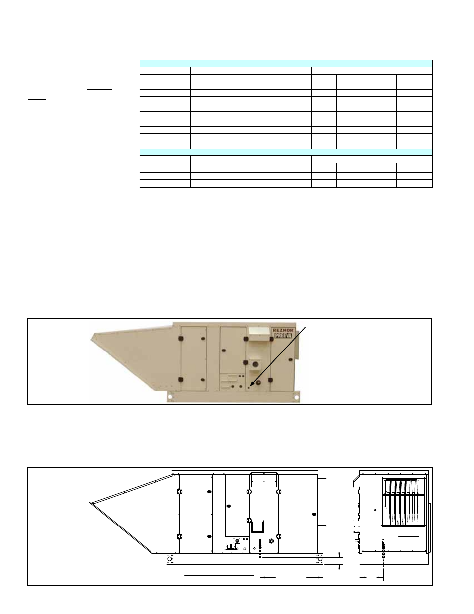
6.2.1 Heat Section Condensate Drain - Model RDH with Option CS2
If Option CS2 was selected, the gas heat section is equipped with a condensate drain
with a 3/8” PVC connection. See location in
FIGURE 14A. This burner condensate
drain is required when one or both of these situations exists:
• A cooling coil is installed upstream of the heat section.
• The temperature rise for a makeup air unit is equal to or less than 60°F.
6.2 Heat Section
Condensate
Drain(s) - Models
RDH and RHH
1/2” Male NPT connection for
installer to connect a drain
line. Put a trap in the line (see
Paragraph 6.6.4) and empty
into a sanitary drain system.
Periodic cleaning of the con-
densate disposal system is
required.
FIGURE 14A -
Location of
Option CS2
Heat Section
Condensate
Drain
Connection -
Model RDH
(Does NOT apply to
AG58 or D12G; see
NOTE on page 19.)
TABLE 13 - BTUH
Inputs and Capacities
by Altitude for Model
RHH
BTUH Inputs and Capacities by Altitude in the UNITED STATES for Model RHH
ALTITUDE
RHH Size130
RHH Size 180
RHH Size 260
RHH Size 350
Feet
Meters
Normal Input
(BTU/HR)
Thermal Output
Capacity (BTU/HR)
Normal Input
(BTU/HR)
Thermal Output
Capacity (BTU/HR)
Normal Input
(BTU/HR)
Thermal Output
Capacity (BTU/HR)
Normal Input
(BTU/HR)
Thermal Output
Capacity (BTU/HR)
0 - 2000
0 - 610
131000
120520
175000
159,250
260,000
236,600
345,000
313,950
2001 - 3000
611 - 915
123140
113289
164500
149,695
244,400
222,404
324,300
295,113
3001 - 4000
916 - 1220
120520
110878
161000
146,510
239,200
217,672
317,400
288,834
4001- 5000
1221 - 1525
117900
108468
157500
143,325
234,000
212,940
310,500
282,555
5001 - 6000 1526 - 1830
115280
106058
154000
140,140
228,800
208,208
303,600
276,276
6001 - 7000 1831 - 2135
112660
103647
150500
136,955
223,600
203,476
296,700
269,997
7001 - 8000 2136 - 2440
110040
101237
147000
133,770
218,400
198,744
289,800
263,718
8001 - 9000 2441 - 2745
107420
98826
143500
130,585
213,200
194,012
282,900
257,439
9001 - 10000 2746 - 3045
104800
96416
140000
127,400
208,000
189,280
276,000
251,160
BTUH Inputs and Capacities by Altitude in CANADA for Model RHH
ALTITUDE
RHH Size130
RHH Size 180
RHH Size 260
RHH Size 350
Feet
Meters
Normal Input
(BTU/HR)
Thermal Output
Capacity (BTU/HR)
Normal Input
(BTU/HR)
Thermal Output
Capacity (BTU/HR)
Normal Input
(BTU/HR)
Thermal Output
Capacity (BTU/HR)
Normal Input
(BTU/HR)
Thermal Output
Capacity (BTU/HR)
0 - 2000
0 - 610
131000
120520
175000
159,250
260,000
236,600
345,000
313,950
2001 - 4500
611 - 1373
117900
108468
157500
143,325
234,000
212,940
310,500
282,555
6.0 Mechanical
(cont’d)
6.1 Gas Piping and Pressures - Models RDH and RHH (cont’d)
6.1.3 High Altitude Operation - Gas-Fired Model RDH or RHH being
installed above 2000 ft (610M) (cont’d)
6.2.2 Condensate
Drain - Model RDH
with Option AG58 or
D12G Modulating Gas
Control
A Model RDH unit with modulating gas control Option AG58 or D12G requires a con-
densate drain from the vent area. The 1/2” PVC connection is underneath the unit; see
FIGURE 15. Since this drain will be used during the heating season, the connection
is under the unit and the drain should be run down through the inside of the roof curb
and into the heated space. Put a trap in the line (Paragraph 6.6.4) and empty it into a
sanitary drain.
11-3/8”(289mm)
30-7/8”
(784mm)
3-3/16”
(81mm)
Control Side View
Front
View
FIGURE 14B - Location
of Condensate Drain
Connection - Model
RDH with Gas Control
Option AG58 or D12G