6 other optional electrical components, 0 electrical (cont’d) – Reznor RXH (Outdoor PreevA) Unit Installation Manual User Manual
Page 48
Form I-RDH/REH/RHH/RXH (12-14), Page 48
TABLE 31 - FLA of
Single Speed, Open
Dripproof Motors
Full Load Amps - Blower Motors (Open)
(Single Speed- Average Values)
HP
1/4
1/3
1/2
3/4
1
1-1/2
2
3
5
115V 1PH
4.6
5.6
8.8
11.0
13.0
18.2
20.4
24.8
N/A
208V 1PH
2.5
3.1
5.1
6.1
7.2
10.1
11.3
13.7
28.0
230V 1PH
2.3
2.8
4.4
5.5
6.5
9.1
10.2
12.4
26.0
208V 3PH
1.7
1.8
2.2
2.9
3.6
5.8
7.3
9.3
14.6
230V 3PH
1.5
1.6
2.0
2.6
3.2
5.2
6.6
8.4
13.2
460V 3PH
.8
.8
1.0
1.3
1.6
2.6
3.3
4.2
6.6
575V 3PH
N/A
N/A
N/A
N/A
1.3
2.1
2.6
3.4
5.3
Venter motor amps for a 115 volt or 575 volt unit are 1.5 amps; venter motor amps for
a 208, 230, or 460 volt unit are .8 amps.
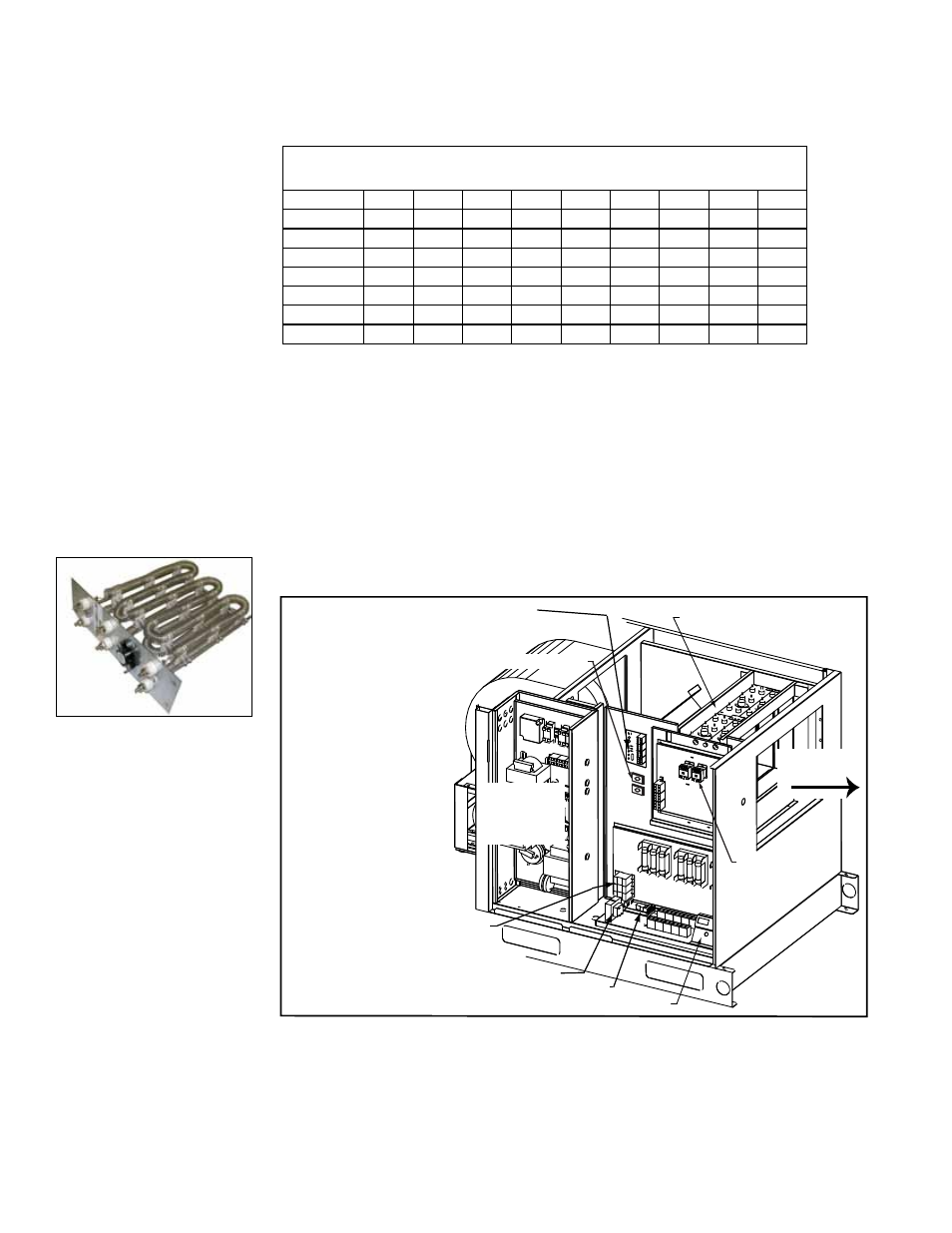
7.5.5 Electrical Heating
Elements - Model REH
Electric heating modules in Model REH are made up of two to six 5kw or three to twelve
10 kw heating elements depending on size and voltage of the unit. The elements are
bracketed together to make up the electric heat section assembly.
The electric heat section has either heating only analog controls (Option EG1 or EG2)
or digital heating/cooing controls (Option D12E or D12D). With Option EG1, operation
of the heating elements is controlled by a single stage thermostat. With Option EG2,
the heat section provides two-stages of heat in response to a two-stage thermostat.
Digital control is either two stage (Option D12E) or modulating (Option D12D).
See Paragraph 8.3.2 and the control instruction form (CP-PREEEVA-D12 B/C/D/E/
F/G) for digital control information.
FIGURE 42A - Sample
of one Electric Heating
Element in the Electric
Heat Assembly
7.0 Electrical
(cont’d)
7.5 Electrical
Operating
Components
(cont’d)
Electric Heat Assy
Fuses
Distribution
Block
Relay
Transformer
Main
Electrical
Box
Discharge
Airflow
Staging Board used in
Control Option D12D
(see Paragraph 8.3.2)
FX06 Controller
Transformer(s)
Contactor(s)
FIGURE 42B -
Electric Heat
Section -
Model REH
7.6 Other Optional
Electrical
Components
7.6.1 Convenience Outlet, Option BC2 - RDH, REH, RHH, RXH
If the unit is equipped with a convenience outlet, it will have an externally accessible,
weatherproof 115 volt, duplex, ground fault outlet on the control side of the cabinet.
A
separate 115 volt power supply is required.
Optional electrical components ordered with the unit are identified on the wiring dia-
gram. For a list of wiring diagram option codes and descriptions, see
APPENDIX, page
65.
amps. See the motor rating plate for exact motor specifications. Do not exceed amp
rating on the motor nameplate.
7.5.4 Blower Motor (RDH/REH/RHH/RXH) and Venter Motor (RDH and
RHH) (cont’d)