Rdh, reh, rhh, and rxh – Reznor RXH (Outdoor PreevA) Unit Installation Manual User Manual
Page 37
Form I-RDH/REH/RHH/RXH (12-14), P/N 215210 R14, Page 37
Drain Trap
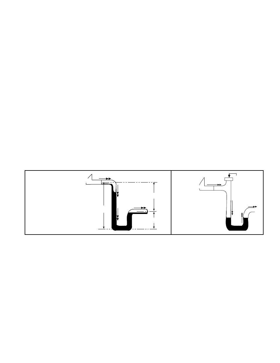
The design of the drain trap is important. Since the condensate drain pan is on the
blower inlet side, there is a negative pressure at the drain relative to the ambient. The
trap height must account for this static pressure difference. Maximum negative static
can be determined by reading the negative pressure at the blower inlet and adding .2”
w.c. to allow for dirty filters.
If dimension “B” is not tall enough, the water seal will not hold and air will be drawn
through the drain pipe into the system. If the outlet leg of the trap is too tall, water will
back up into the drain pan. As condensate forms during normal operation, the water
6.6.4 Cooling Module
Condensate Drain
A removable drain pan with a 1” NPT drain connection is located below the coil cabinet
(See
FIGURE 31 or FIGURE 32A or B). When connecting the drain line, provide a
means of disconnecting the line at or near the cabinet connection to allow the drain
pan to be removed for cleaning.
Ensure the system is level and
install a trap in the drain (see FIGURE 33A). Pitch the
drain line at least 1/2” (13mm) for every 10 feet (3M) of horizontal run. Drain lines must
not interfere with drain pan or access panels. An obstruction in the drain or a poorly
designed drain can cause the condensate pan to over flow which could result in unit
or building damage.
If the installation or local code requires, run drain into a waste water system.
To prevent air
from entering
always close
the cleanout.
Water Flow
Unit
FIGURE 33B -
Drain Trap
with Cleanout
B
A
A/2
C
L
C
L
C
L
Unit
Water Flow
Water Flow
A = 1” (25mm) for
each 1” (25mm)
of maximum
static pressure
plus 1” (25mm)
B = A + A/2
FIGURE 33A -
Condensate Drain
Trap Dimensions
Seasonal Usage - At the beginning of the cooling season, inspect and clean the entire
cooling coil cabinet including the condensate drain pan. Thoroughly clean dirt, algae,
grease, and other contaminates. Inspect condensate drain pans, traps, and piping; fill
traps with water to ensure proper operation. During a winter shutdown of the cooling
system, it may be desirable to disconnect and remove all water from the trap and drain
to prevent freeze damage. If local building codes permit, trap may be filled with an anti-
freeze solution. Or, piping may be designed with freeze plugs or other freeze protection
methods (such as a heat tape).
Year Round Usage - Climates or applications with cooling requirements year round
require more frequent inspections of the cooling coil cabinet and condensate drains.
Condensate Drain Use
level in the trap rises until there is a constant outflow.
FIGURE 33A illustrates the
appropriate dimensions for trapping a negative pressure system.
Improper trap design accounts for some condensate drainage system failures, but
incorrect use and maintenance of condensate drain traps can also cause problems.
The combination of airborne particles and moisture in the air handler can result in
algae formation in the drain pan and traps. The traps must be cleaned regularly to
avoid blockage that can slow or stop water flow, resulting in backup into the system.
If the drains have a cleanout opening (
FIGURE 33B), be sure to close the opening
after cleaning.
If the system is ordered with a Reznor
®
Model XBWU energy recovery module, the
module is shipped separately for field installation. The unit should have been ordered
with a duct flange (Option AR5) and with the optional wiring needed (Option BB8).
The transition duct is field supplied. The roof curb for the energy recovery module is
for the energy recovery module only and is either optional with the module or field
supplied. Follow the installation instructions with the energy recovery module and the
wiring diagram on the unit.
6.7 Optional Energy
Recovery Module
(field-installed) -
RDH, REH, RHH,
and RXH