Reznor RXH (Outdoor PreevA) Unit Installation Manual User Manual
Page 19
Form I-RDH/REH/RHH/RXH (12-14), P/N 215210 R14, Page 19
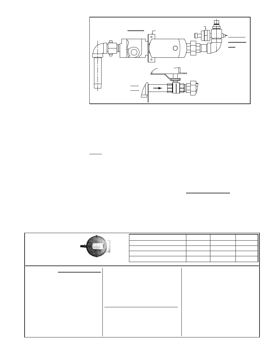
Top View
Side
View
Ball Valve
Actuator
Ball Valve
Actuator
Combination
Single-Stage
Gas Valve
Pressure
Tranducer
Ball Valve
Gas Valve
Bracket
Orifice
Manifold
Pressure
Tap
FIGURE 12 - Gas
Manifold with Gas
Control Options AG58
and D12G
6.1.3 High Altitude
Operation - Gas-Fired
Model RDH or RHH
being installed above
2000 ft (610M)
Adjustments for High
Altitude Operation
(does not apply to Models
RDH and RHH with
Option AG58 or D12G)
After an adjustment is made, cycle the heat section. Re-check the outlet pressure of
the valve and the manifold pressure. When pressure is correct for highest fire, remove
the manometers and replace the caps. Check for a leak at the pressure tap fittings.
3) Lowest fire manifold pressure is regulated by the ball valve actuator in response to
signals from the ignition control board. The ball valve was set at the factory and should
not need to be checked at startup. For future reference, instructions for checking low-
est fire pressure are in Form O-PREEVA included in the literature bag.
NOTE: Altitude adjustment does NOT apply to Model RDH or RHH with Gas Con-
trol Option AG58 or D12G -- Modulating gas control Options AG58 and D12G DO
NOT require a gas pressure adjustment derate for high altitude. The patented
control system works on a principle of safe, continuous gas and combustion air moni-
toring and adjustment. As the mass flow through the combustion system changes, due
to the lower oxygen level at high altitude, the control system senses the change, auto-
matically reducing the firing rate of the burner.
If the heater is being installed at an elevation above 2000 ft (610M), check the rat-
ing plate to verify that the heater is factory-equipped for the elevation at the installation
site.
If the elevation on the rating plate matches the elevation of the installation
site, field adjustment for high altitude is not required.
If the rating plate does not match the elevation of the installation site, high altitude
adjustment will need to be done as part of the startup procedure. (High altitude adjust-
ment can only be done while the unit is operating.) During startup, follow the instruc-
tions in this section to adjust the valve outlet pressure.
FIGURE 13 -
High Altitude
(>6000ft/1830M)
Pressure Switch
Requirement
Pressure Switch
NOTE: If unit is above 6000 ft (1830M)
elevation and the following conditions
apply, installation of a high altitude pres-
sure switch is required. If a replacement
switch is needed, contact your distributor
for the switch and follow the instructions
below to install the high altitude pressure
switch before starting the heater.
□
Elevation on the rating plate is not
above 6000 ft (1830M)
□
Unit has a single or two-stage gas
control (Option AG1, AG2, AG3, AG15,
AG16, AG60, DG1, DG5, or D12C).
NOTE: If equipped with a two-stage
control with a two-speed venter
(Options AG8, AG9, AG9H, AG60,
AG61, AG62, DG1, DG5, and D12C),
there are two pressure switches. Only
the high speed pressure switch needs
to be changed.
Instructions for changing pressure switch:
1. If the unit is installed, turn off the gas
and the power.
2. In the control compartment, locate
the pressure switch that needs to be
replaced. (
NOTE: If there are two
pressure switches, the high speed
switch to be replaced is toward the top
of the unit.)
3. Mark and disconnect the two wires
attached to the pressure switch.
4. Mark and disconnect the sensing
tube(s) from the pressure switch.
5. Locate the two screws holding the
switch mounting bracket. Remove the
pressure switch. Save the screws.
6. Using the same screws, install the
high altitude pressure switch. Attach
sensing tube(s) and wires.
7. If installed, turn on the power and the
gas.
Above 6000 ft (1830M)
Switch P/N Label Color Setting
RDH 75, 100
197031
Purple
0.35” w.c.
RDH 125
197032
Pink
0.45” w.c.
RDH 150
197029
Lt Blue
0.60” w.c.
RDH 175-400 & RHH all Sizes
201160
Brown
1.05” w.c.