0 mechanical (cont’d) – Reznor RXH (Outdoor PreevA) Unit Installation Manual User Manual
Page 18
Form I-RDH/REH/RHH/RXH (12-14), Page 18
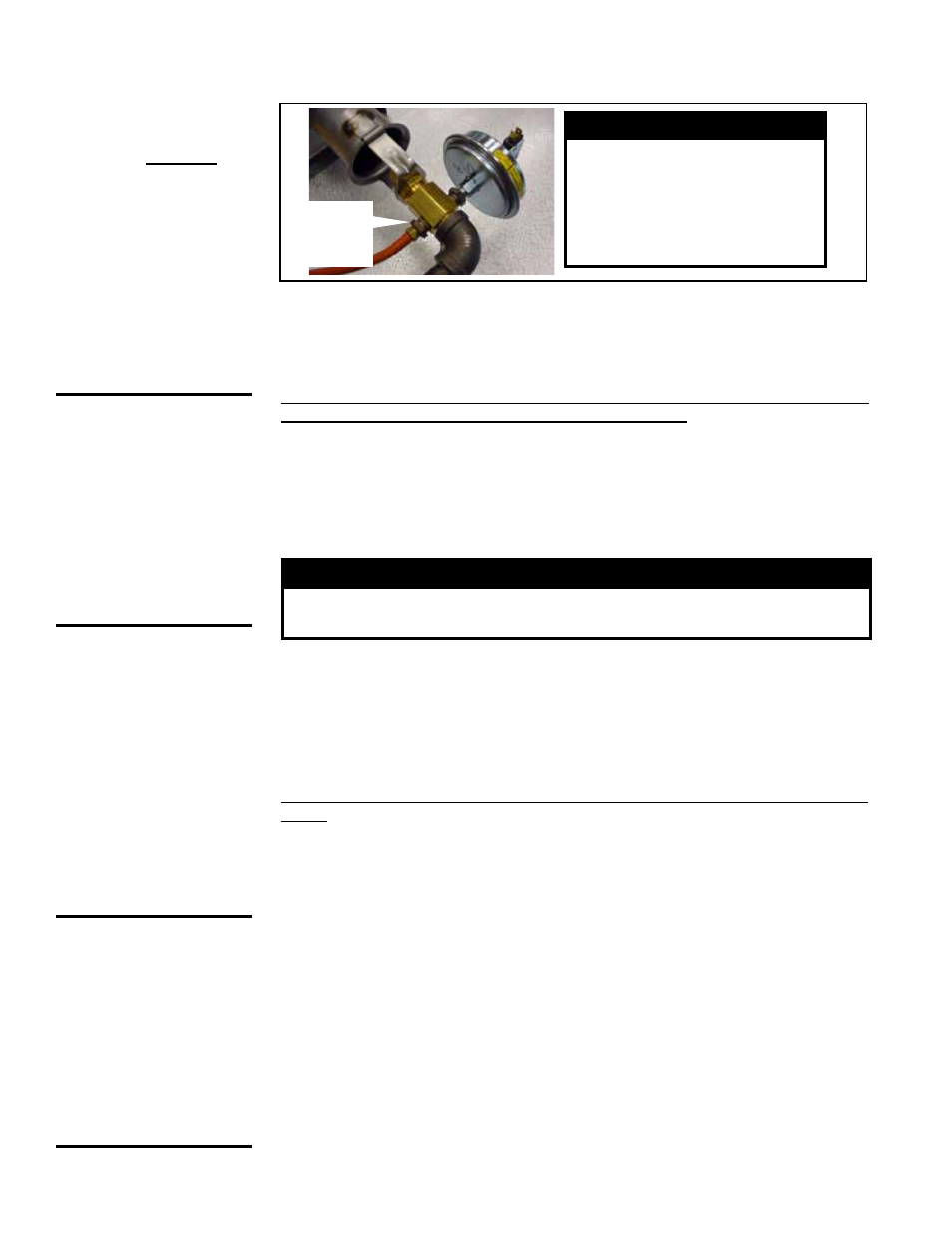
FIGURE 11C - Pressure
Tap Location for
Measuring Low Fire
Outlet (Bypass)
Pressure -- Electronic
Modulation Gas Control
Options AG8, AG9,
AG9H, AG40, DG2, DG6,
and D12B
WARNING
Measure low-fire pressure at
this location only for units
with electronic modulation
gas control Option AG8, AG9,
AG9H, AG40, DG2, DG6, or
D12B).
1/4” NPT
Pressure
Tap
2) Measure High Fire Pressure and Adjust (if needed)
Open the manual valve and operate the heater.
Using the manometer connected to the single-stage valve, measure the outlet pres-
sure. To ensure an accurate high-fire gas pressure reading at the single-stage valve, a
minimum 20VDC signal MUST be present at the modulating gas valve.
Normally, when operating at the altitude indicated on the rating plate, adjust-
ments to the factory settings should not be necessary. If adjustment is required,
remove the cap from the adjustment screw on the single-stage valve. Adjust pressure
setting by turning the regulator screw IN (clockwise) to increase pressure. Turn regu-
lator screw OUT (counterclockwise) to decrease pressure. If an adjustment is made,
turn up the thermostat. Cycle the burner once or twice to properly seat the adjustment
spring in the valve. Re-check the pressure. When the outlet pressure is right for the
installation, remove the manometer and replace the cap. Check for a leak at the pres-
sure tap fitting.
WARNING
Valve outlet gas pressure must never exceed the value listed
in TABLE 11 (or as shown on the rating plate).
3) Measure Low Fire (Bypass) Pressure
To measure low-fire (bypass pressure) on electronic modulation gas control Options
AG8,AG9, AG9H, AG40, DG2, DG6, and D12B, disconnect one of the wire leads to the
modulating valve. Measure the pressure with the manometer attached to the pressure
tap just behind the orifice adapter (
FIGURE 11C). Re-connect the wire.
DO NOT attempt to adjust the bypass (low-fire) pressure. If bypass pressure is incor-
rect (see
TABLE 11, page 20), contact the factory.
CAUTION: DO NOT
bottom out the gas
valve regulator
adjusting screw.
This can result in
unregulated manifold
pressure causing
excess overfire and
heat exchanger
failure.
CAUTION: DO NOT
bottom out the gas
valve regulator
adjusting screw.
This can result in
unregulated manifold
pressure causing
excess overfire and
heat exchanger
failure.
6.0 Mechanical
(cont’d)
6.1 Gas Piping and Pressures - Models RDH and RHH (cont’d)
6.1.2 Checking Burner Gas Pressure (cont’d)
INSTRUCTIONS for ELECTRONIC MODULATION Gas Control Options AG58 and
D12G)
1) Measure the Manifold Pressure
Turn the manual valve in the gas line off.
Locate the manifold pressure tap; see
FIGURE 12. Remove the bushing and connect
a manometer to the 1/8" pressure tap.
Turn on the manual gas valve. Operate the unit with a call for heat. Verify that the
actuator has fully opened the ball valve (highest fire). The ball valve is fully open when
the dash marks on the actuator are aligned with the gas piping. With the burner at high-
est fire, measure the manifold pressure. The manifold pressure should be 3.4" w.c. for
natural gas or 10” w.c. for propane.
2) Adjust Pressure at the Single-Stage Valve (if needed)
Turn the manual gas valve off. On the single-stage gas valve (see FIGURE 11A,
page 17), locate the 1/8” output pressure tap and attach a manometer.
Turn on the manual gas valve. Operate the unit with a call for heat. Check the outlet
pressure of the valve with the burner at full fire. Pressure should be 3.5” w.c for natural
gas or 10” w.c. for propane.
If adjustment is necessary, remove the cap from the
adjustment screw. Set pressures to correct setting by turning the regulator screws IN
(clockwise) to increase pressure. Turn regulator screws OUT (counterclockwise) to
decrease pressure.