0 mechanical (cont’d), Table 21 - evaporative cooling module dimensions – Reznor RXH (Outdoor PreevA) Unit Installation Manual User Manual
Page 32
Form I-RDH/REH/RHH/RXH (12-14), Page 32
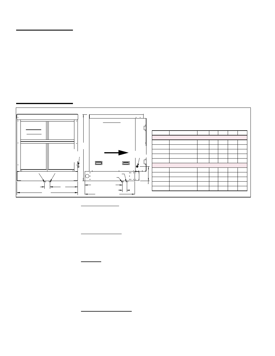
Water Supply - Connect the water supply to the 1/2” NPT male connection on the
control side of the evaporative cooling module. See location in
FIGURE 25. Install a
manual water shutoff valve upstream of the cooling module inlet at a convenient non-
freezing location. If necessary, install a bleed line between the manual valve and the
cooling module to allow drainage of the line between the shutoff valve and the cooling
module.
Fill and Drain Kits (field installed) - If the module has a pump and float water control
system and is ordered with a fill and drain kit (Option CT1, CT2, or CT3), refer to the
illustration in
FIGURE 26, page 33, to install the automatic fill and drain valves. Refer
to the system wiring diagram to make wiring connections.
CAUTION: Water
reservoir must be
drained and pump
motor turned off
when outside
temperature falls
below 32°F (0°C).
Pump must never
be operated without
water in the reservoir.
See Hazard Levels,
page 2.
FIGURE 25 - Evaporative Cooling Module Dimensions and Water Connection Locations
A
C
B
Water
Connection
1/2” NPT
Removable Panel -
Control and Media
Access
Side View
Entering
Air View
Overflow
Connection,
3/4” NPT Male
Drain
Connection,
3/4” NPT Male
Drain
Overflow
Water
Connection
Airflow
3 (76)
20-7/8 (531)
2-1/2 (64)
27-3/4 (705)
7-15/16
(202)
TABLE 21 - Evaporative Cooling Module
Dimensions
RDH
REH
RHH
RXH
A
B
C
Dimensions - inches
75/100
10A/20A/40A
N/A
000A 33-3/4 34-1/2 15-3/8
125/150
15B/30B/60B
N/A
000B 43-3/4 34-1/2 20-3/8
175/200/225
N/A
130/180 000C 33-3/4 43-3/4 15-3/8
250/300
30D/60D/90D/120D
260
000D
50
43-3/4 23-1/2
350/400A
40E/80E/120E
350
000E
58
43-3/4 27-1/2
Dimensions - mm
75/100
10A/20A/40A
N/A
000A 857
876
391
125/150
15B/30B/60B
N/A
000B 1111
876
518
175/200/225
N/A
130/180 000C 857
1111
391
250/300
30D/60D/90D/120D
260
000D 1270 1111 597
350/400A
40E/80E/120E
350
000E 1473 1111
699
Follow these instructions to field connect the water supply and make necessary checks
and adjustments before operating the evaporative cooling module.
NOTE: See TABLE 5, page 10 for evaporative cooling module weights.
6.0 Mechanical
(cont’d)
6.5 Optional Evaporative Cooling Module (factory installed)
(cont’d)
Freeze Protection - If a freeze protection option was ordered, the fill valve will not
operate at subfreezing temperature.
NOTE: On an evaporative cooling module with a
recirculating pump and float water control system, freeze protection is only available
if an optional fill and drain kit is field installed. See
Operating Sequence Section in
FIGURE 26, page 33.
Overflow and Drain - All evaporative cooling modules are equipped with an overflow
and drain fitting. The fittings are in the cabinet bottom and come complete with a lock
nut and a sealing gasket. Check these fittings for tightness before installing the over-
flow and drain piping. The drain and overflow fitting will accommodate 3/4” NPT fittings
and are also tapped with a 1/2” female pipe thread for iron pipe.
Bleed Off - If the module has a recirculating pump and float water control sys-
tem, it has a bleed off hose. The bleed off hose is attached to a tee in the fill line and
must drain into the overflow drain. Make sure that the end of the bleed off line extends
into the overflow drain. Adequate bleed off is important to maintaining an efficiently
operating system by lessening the concentration of undesirable minerals in the water
being circulated through the cooling module. Minerals buildup because evaporation
only releases “pure water vapor” causing the concentration of contaminants in the
water to increase as the evaporation process continues. The minerals accumulate on
the media, in the water lines, on the pump, and in the reservoir.
Water Hammer Arrestor - If the cooling module is equipped with an AquaSaver
timed metering system, the operation of the solenoid valve in the water line is con-
trolled by the timer. Due to various water pressures and installation conditions, the
water supply line may bang abruptly when the solenoid valve closes. This banging can
be minimized by installing an optional water hammer arrestor (Option ECB1) in the
supply line. When installing an optional water hammer arrestor, select an indoor loca-