0 controls and operation, 1 gas valve - model rdh and model rhh, 0 electrical (cont’d) – Reznor RXH (Outdoor PreevA) Unit Installation Manual User Manual
Page 50
Form I-RDH/REH/RHH/RXH (12-14), Page 50
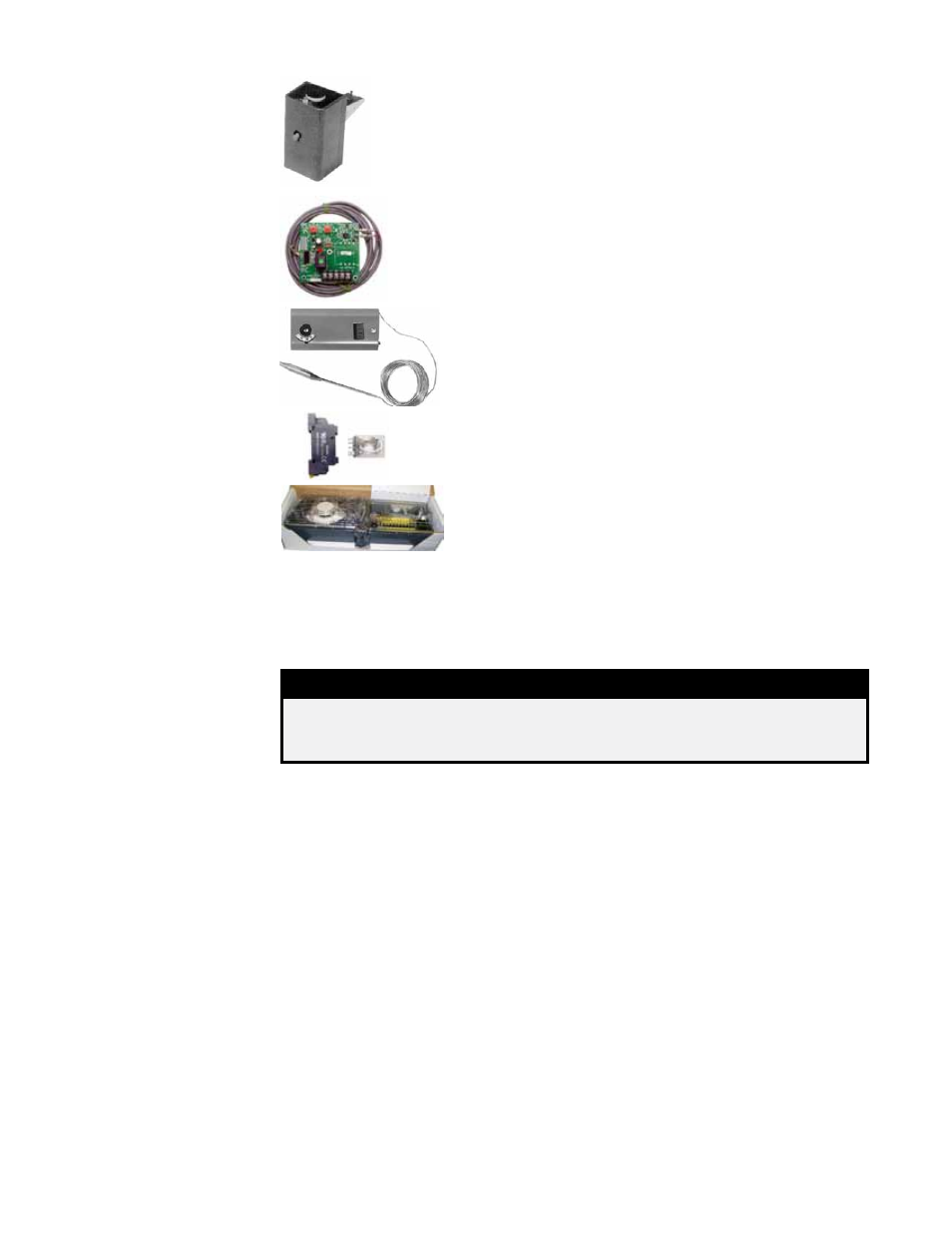
Option BD4 (factory-installed) or Option BD5 (field-installed) 200°F fir-
estat is
P/N 42782. Firestat Option BD4 is factory installed in the mixing
box to sense the temperature of the return air. Firestat Option BD5 is
shipped separately for field installation in the discharge ductwork.
The firestat will shutdown the unit if temperature setpoint is reached.
Comply with local building codes.
7.6.4 Firestat, Option
BD4 or BD5 - RDH,
REH. RHH, RXH
Limit control,
P/N 211480, is factory installed to monitor the tempera-
ture of the discharge air. Setpoint of automatic reset control is adjust-
able. (
NOTE: Not needed with digital controls; standard function of
the digital controller.)
7.6.5 Discharge
Temperature Low Limit
(Freezestat), Option
BE2 - RDH, REH, RHH,
RXH
7.6.6 High Ambient
Limit Control (burner
cutoff), Option BN2 -
RDH, REH, RHH, RXH
The high ambient limit control monitors the temperature of
the outside air and activates to shutoff the burner if the set-
point is reached. The control has an adjustable setpoint and
resets automatically.
P/N is 126170.
A DPDT plug-in relay is installed for coordination of unit opera-
tion with the operation of the building exhaust fan. Plug-in relay
P/N is 211411; socket P/N is 211415.
7.6.7 Exhaust Fan Interlock
Relay, Option BG9 - RDH,
REH, RHH, RXH
7.0 Electrical (cont’d)
7.6 Other Optional Electrical Components (cont’d)
This photoelectric smoke detector is shipped separately to
be installed in the discharge ductwork. Follow installation
instructions supplied with the control and the wiring on the
unit wiring diagram. Comply with local building codes. P/N
of the device is
159553.
7.6.8 Smoke Detector,
Option SA1 - RDH,
REH, RHH, RXH
8.0 Controls and
Operation
Gas-fired furnaces are equipped with a 24-volt combination valve which includes the
automatic electric on-off valve the pressure regulator, the safety pilot valve, and the
manual shutoff valve. Valve on/off function is controlled by the room thermostat or
digital controller.
8.1 Gas Valve - Model RDH and Model RHH
WARNING
The operating valve is the prime safety shutoff. All gas supply lines
must be free of dirt or scale before connecting the unit to ensure
positive closure. See Hazard Levels, page 2.
8.2.1 Single-Stage Operation - Recirculated Heating Only (Option AG1
applies to Model RDH and Model RHH; Option EG1 applies to Model REH)
The single-stage gas valve on Models RDH and RHH allows for single-stage control
from a single-stage, 24-volt thermostat. On Model REH, the heating elements are con-
trolled by a single-stage, 24-volt thermostat.
The thermostat can either be selected as an option or be field supplied. Follow the
thermostat manufacturer’s instructions for installation. Make wire connections accord-
ing to the wiring diagram.
8.2 Analog Controls
for Heating or
Heating/Makeup
Air
8.2.2 Two-Stage
Operation -
Recirculated Heating
Only (Option AG2 applies
to Model RDH and Model
RHH; Option EG2 applies
to Model REH)
On Models RDH and RHH, a two-stage combination gas control valve provides for
low fire (70%) or high fire (100%) operation controlled by a two-stage thermostat.
First stage (low fire) is factory set. Both high and low stages are controlled by a Servo
regulator, maintaining constant gas input under wide variations in gas supply pressure.
See instructions packed with the unit for specific gas valve specifications, wiring, and
operating instructions.
On a Model REH, staging of heat from the heating elements is controlled by the two-
stage thermostat.
A two-stage thermostat can either be selected as an option or be field supplied. Follow
the thermostat manufacturer’s instructions and the wiring diagram.