0 mechanical (cont’d) – Reznor RXH (Outdoor PreevA) Unit Installation Manual User Manual
Page 34
Form I-RDH/REH/RHH/RXH (12-14), Page 34
6.5.2 Adjusting Water Flow Over Pads
Proper water flow over the evaporative cooling media is critical to extend the life and
maintain the
efficiency of the pads. Read the warnings and follow the instructions that
apply.
CAUTION: Do not flood the media pads with extreme quantities of
water for long periods as this will cause premature breakdown of
the media. An even flow from top to bottom of the media with the
least amount of water is all that is required to assure maximum
efficiency and media life span. More water does not provide more
evaporation or more cooling.
WARNING
Adjust ball
valve only when
the power is
disconnected from
the system. Failure
to do so can cause
electrical shock,
personal injury, or
death.
Adjusting Water Flow with a Float and Pump Control System - Using the ball
valve, located in the length of hose running from the pump to the distribution line inlet
(See
FIGURE 28), adjust the valve handle to allow the flow to completely dampen the
media pads from top to bottom.
Operate the unit watching the water flow. After 15 minutes with the blower in operation,
the water should have completely dampened the pads but should not be flowing off the
entering side of the media. If water is flowing off the entering side of the media, turn the
system off, disconnect the power, and reduce the entering water flow.
Adjusting Water Flow with a Timed Metering Control System - NOTE: Water flow
and pad wetting time should be adjusted at maximum airflow and wet bulb depression
to assure complete wetting of the media at the extreme operating conditions.
In addition to adjusting water flow, the timing of the water on/off cycle can be adjusted.
Adjustments are correct when
l) the water rises from the holes in the sprinkler pipe
consistently along the entire pipe length,
2) the media pads wet evenly after a few “ON”
cycles (no dry spots or dry streaks), and
3) a slight amount of excess water collects at
the drain at the completion of the “ON” cycle.
FIGURE 28 - Remove
side door and locate
ball valve (illustration
below is from the
rear). Both water flow
control systems have
a ball valve in the
water line.
Ball
Valve,
P/N
207468
PVC Sprinkler Pipe
RDH
Size
REH
Size
RHH
RXH
Size
A = Water rise from
PVC Sprinkler Pipe
75/100/
125/150
10A/20A/40A/
15B/30B/60B
N/A
000A/
000B
1/8” to 1/2”
3 to 13mm)
175/200/
225/250/
350/ 400A
30D/60D/90D/
120D/40E/80E/
120E
130/180/
260/350
000C/
000D/
000E
1/4” to 1/2”
(6 to 13mm)
FIGURE 29 - Timed Water System - Use the ball valve in FIGURE 28 to
adjust the rise from the distribution (sprinkler) pipe in the evaporative
cooling module.
1) AquaSaver Water Flow Adjustment - Using the ball valve illustrated in FIGURE
28, adjust the water flow so that the water rises above the distribution pipe as illus-
trated in
FIGURE 29.
A
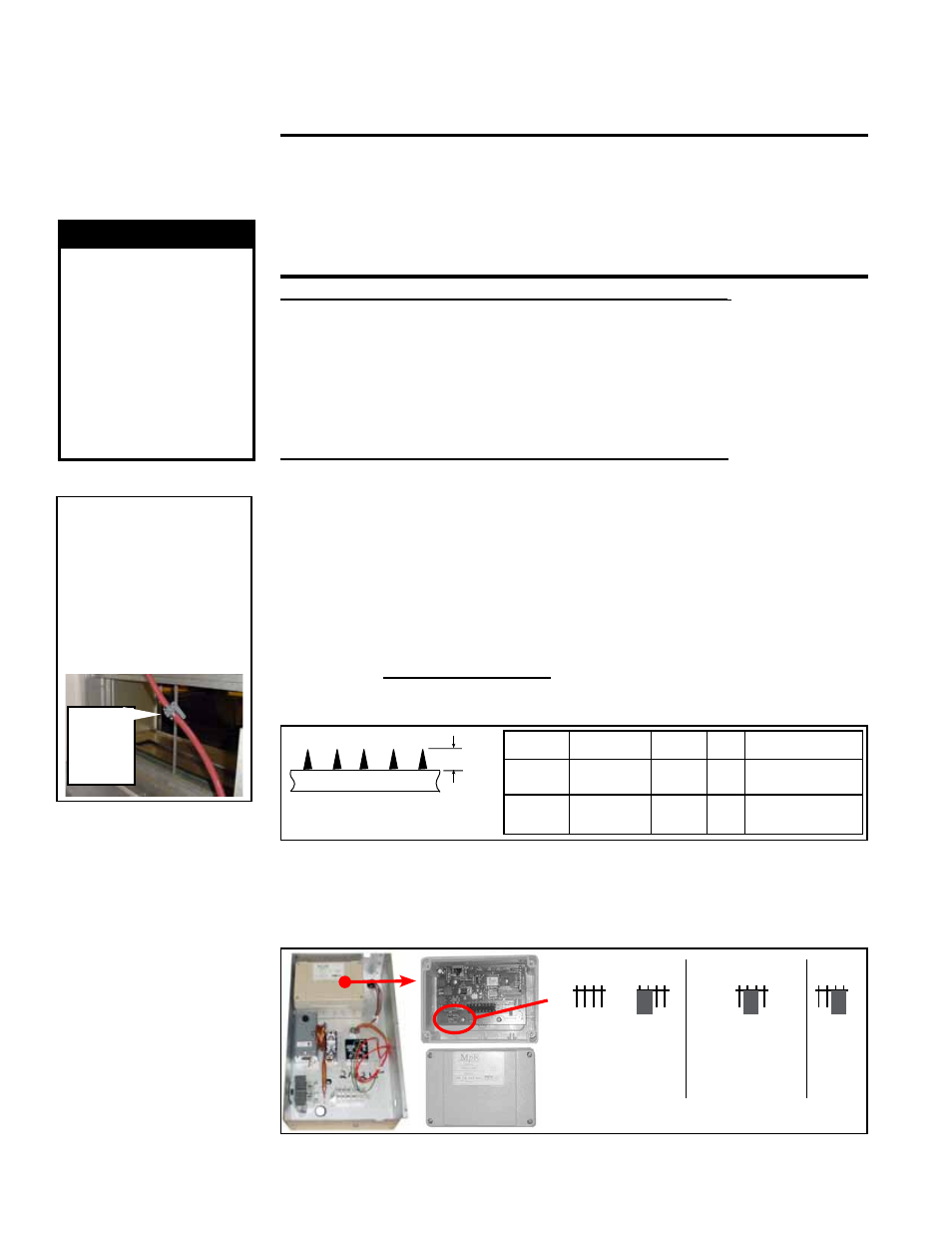
2) AquaSaver Timer Adjustment - At any given temperature, the media pads should
completely wet from top to bottom during the ON cycle. The microprocessor has three
preset timing settings based on media size. The appropriate setting is selected by
changing the position of the suitcase jumper at J2 on the microprocessor. Remove the
cover to check the setting (See
FIGURE 30).
FIGURE 30 - AquaSaver
Microprocessor
Control, P/N 205044, in
the Junction Box
J2
1 2 3 4
1 2 3 4
1 2 3 4
1 2 3 4
S
M
L
RDH 75/100/
125/150
REH 10A/20A/
40A/15B/
30B/60B
RXH 000A/000B
RDH 175/200/225/ 250/
275/300/350/400A
REH 30D/60D/90D/
120D/40E/80E/120E
RHH 130/180/260/350
RXH 000C/000D/000E
If the jumper is at the appropriate location, replace the cover. If the jumper needs to be
moved, move it to the appropriate setting. The setting will go into effect when the power
6.0 Mechanical
(cont’d)
6.5 Optional
Evaporative
Cooling Module
(factory installed)
(cont’d)