Reznor RXH (Outdoor PreevA) Unit Installation Manual User Manual
Page 41
Form I-RDH/REH/RHH/RXH (12-14), P/N 215210 R14, Page 41
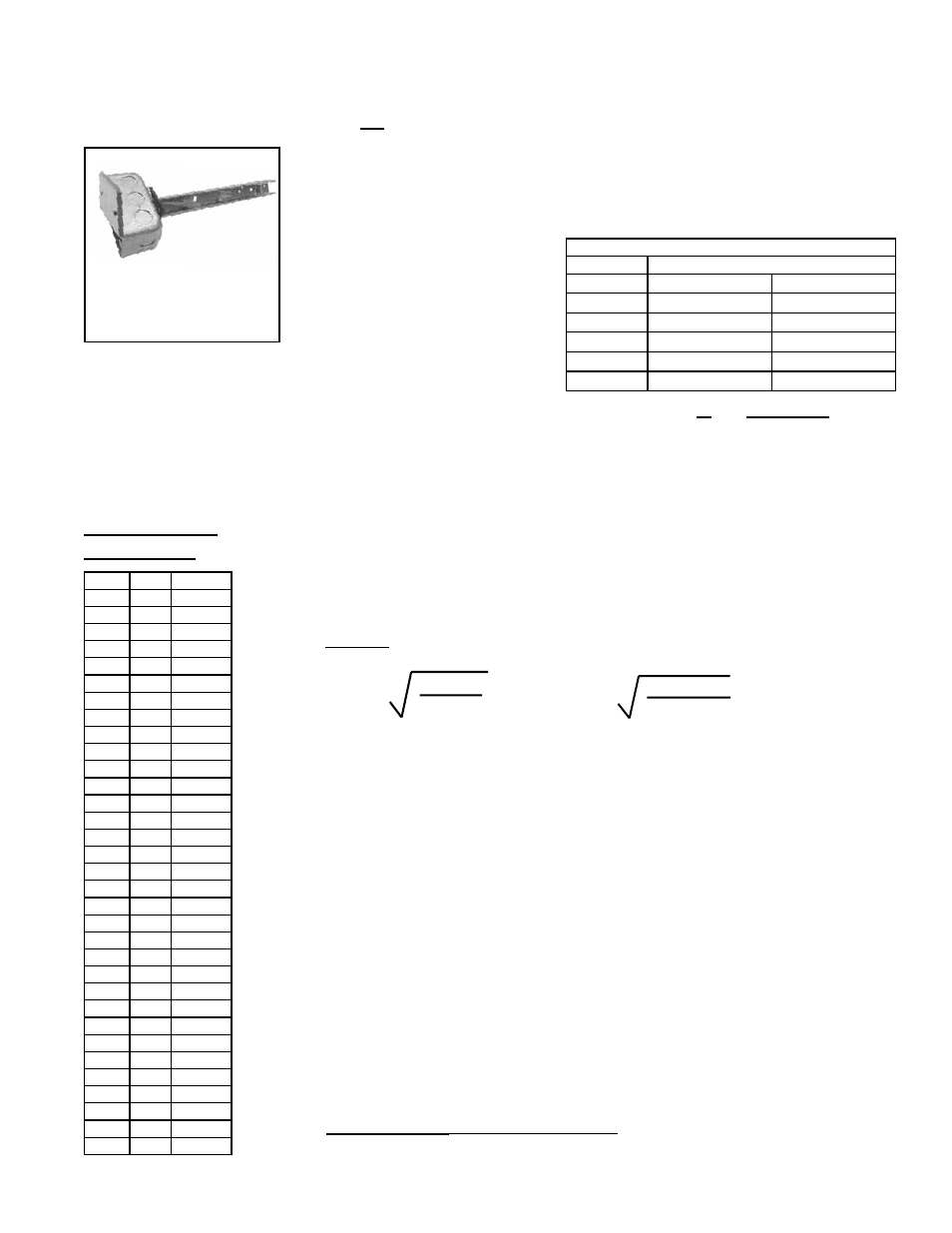
FIGURE 38 - Discharge
Air Sensor Holder,
P/N 115850, used in
Makeup Air Installations
Secure sensor in clip.
Position holder so that it
shields sensor from direct
airflow.
TABLE 26A - Digital Control
Signal Wire Gauge and Length
Maximum Sensor Wire Length for less than 1°F Signal Error
Wire Gauge
Maximum Sensor Wire Length (Digital Control)
AWG
Feet
Meters
14
800
244
16
500
152
18
310
94
20
200
61
22
124
38
bundled separately from the 24 VAC control wiring. The shield must be drained at
the unit and taped on the opposite end.
See
TABLE 26A for wire gauge and length requirements of digital control signal wiring.
(
NOTE: Sensor wire supplied
with the FX05 digital controller is
22AWG. There is no sensor wire
supplied with the FX06 controller;
it must be field supplied.)
connected to the main digital controller should be routed to the unit in one of the fol-
lowing manners:
•
In separate conduits, isolated from 24 VAC controls and line voltage power to the
unit,
OR
•
If the main controller sensor wires are to be run in the same conduit as the 24
VAC control wiring, the sensor wiring must be completed using shielded cable and
TABLE 26B - Sensor
Data for Johnson A99
Series Temperature
Sensors used in DG
and D12 Options -
Resistance VS
Temperature
°F
°C
Ohms
-40
-40
613
-31
-35
640
-22
-30
668
-13
-25
697
-4
-20
727
5
-15
758
14
-10
789
23
-5
822
32
-0
855
41
5
889
50
10
924
59
15
960
68
20
997
77
25
1035
86
30
1074
59
35
1113
104
40
1153
113
45
1195
122
50
1237
131
50
1279
140
60
1323
149
65
1368
158
70
1413
167
75
1459
176
80
1506
185
85
1554
194
90
1602
203
95
1652
212
100
1702
221
105
1753
230
110
1804
239
115
1856
248
120
1908
Instructions for Installing Discharge Air Sensor in the Ductwork
1. Installation requires the discharge air sensor holder including the box cover.
2. Determine a location in the ductwork to install the sensor. Select a location a
sufficient distance from the outlet to provide a good mixture of discharge air
temperature. If installing Options AG3 or AG60 with a capillary sensor, determine
the location based on the length of the capillary tubing.
If installing wiring to the sensor, select a location a sufficient distance from the
outlet to provide a good mixture of discharge air temperature. According to the
latest edition of AMCA Standard 201, in straight ducts, the air is typically well
mixed a minimum of five equivalent duct diameters from the discharge of the unit
with equivalent duct diameter defined as equal to the square root of 4AB/3.14. “A”
and “B” are the duct cross-sectional dimensions.
Example:
Supply ductwork cross-sectional dimension is
24" x 12" (610mm x 305mm).
5 x
4 x 12 x 24
3.14
= 96"
5 x
4 x 305 x 610
3.14
= 2435mm
Solution: Locate the sensor a minimum of 96" (2435mm)
from the outlet of the unit.
NOTE: If the length of the discharge duct is less than 8 ft (2.4M), a mixing vane is
recommended for mixing the discharge air.
Do not mount the sensor in the ductwork after a split in the supply as that will
cause loss of control in the duct that does not house the sensor.
3. The position of the sensor holder is important. The holder will extend 9-3/16”
(233mm) into the ductwork.
In horizontal ductwork, locate the sensor assembly in the top, middle of the duct
with the sensor probe extending vertically down into the center of the airstream.
In vertical ductwork, locate the sensor assembly in the middle of the side of the
duct that corresponds with the top middle of the discharge outlet.
Turn the holder so that the element will be shielded from direct airflow and will
sense the air temperature as it flows through the holes in the holder.
At the selected location in the ductwork, mark the diamond-shaped hole required
for the sensor holder. Cut the hole no larger than required, approximately 1” x 1”
(25mm x 25mm).
4. The procedure for installing the sensor and attaching the holder depends on
whether the sensor is a capillary or an electrical sensor. Follow the instructions
that apply.
Capillary Sensor (Option AG3 and AG60) - Locate the sensor capillary and run
it out through the hole in the discharge panel of the heater. Determine where the
sensor capillary should enter the box and remove the knockout. Put the capillary