3 venting - models rdh and rhh – Reznor RXH (Outdoor PreevA) Unit Installation Manual User Manual
Page 23
Form I-RDH/REH/RHH/RXH (12-14), P/N 215210 R14, Page 23
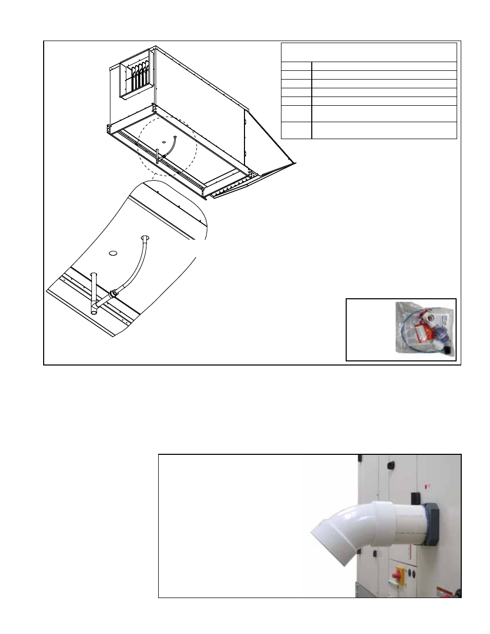
6.2.3 Heat Section Condensate Drains - Model RHH High Efficiency Unit
FIGURE 15 -
Bottom
View of a
Model RHH
showing
Location
of the Heat
Section
Condensate
Drains
(A)
(B)
Insulate tubing
and attach it into
the drain at
the “T”.
Parts Provided (Shipped Separately) for
Installing Condensate Drains
P/N
Description
271064 Freeze-Resistant Condensate Drain Trap
205037 1/2” Schedule 40 Tee
105944 1/2” Schedule 40 Female Adapter
105948 1/2x1/2 Nylon Hose Barb (male)
271183 36” length of pipe insulation (for insulating
the drain hose)
271184 36” length of pipe insulation (for insulating
the 1/2” PVC drain pipe)
Instructions for Installing Model RHH
Heat Section Condensate Drains
NOTE: All PVC drain pipe is provided by the
installer. Depending on the installation, a field-
provided or optional heat tape may be needed.
6.3 Venting - Models
RDH and RHH
6.3.1 Venting - Model RHH
Model RHH has a high efficiency condensing heat section. The heat section vents
through a Schedule 40 PVC pipe that extends from the side of the unit as shown
in
FIGURE 16. The vent must be terminated with an installer-provided 45° elbow of
Schedule 40 PVC or CPVC vemt pipe.
NOTE: In Canada, all PVC vent pipe must be
approved to ULC S636.
Attach the elbow in the orientation illustrated so that the flue products are directed
downward.
FIGURE 16 - Terminate the
vent with a 45° Schedule 40
PVC elbow in the orientation
illustrated. Flue products must
be directed downward.
1) Determine the length of field-provided 1/2” PVC pipe needed
at
(A). At location (A), connect the PVC pipe to the coupler
on the condensate drain in the unit. Slide the pipe insulation
(shipped-separate parts above) over the 1/2” PVC pipe and up
over the joint at
(A). Secure the insulation so that it will continue
to cover the joint at
(A). Cut off any excess.
Freeze
Resistant
Trap,
P/N 271064
2) At the end of the pipe, location (B), position the Schedule 40 tee (from
shipped-separate parts) as illustrated and attach. Extend the tubing from
the second drain toward the tee. Determine the length of PVC pipe needed
to allow the tubing to be attached. Attach the length of PVC pipe to the tee.
From the shipped-separate items, attach the female adapter to the pipe
and the hose barb to the adapter. Slide the smaller piece of insulation over
the tubing and up into the unit. Secure
the insulation. Attach the thetubing to
the hose barb.
3) Attach PVC drain to the “T”. Downstream from the “T”,
install the freeze resistant trap,
P/N 271064 (shown right).
Follow the manufacturer’s instructions to install and maintain
the trap. Continue the line from the trap into a sanitary drain.