0 mechanical (cont’d) – Reznor RXH (Outdoor PreevA) Unit Installation Manual User Manual
Page 30
Form I-RDH/REH/RHH/RXH (12-14), Page 30
Enthalpy Sensor(s)
Installation
Instructions:
NOTE: Attach the outside
air sensor when installing
the outside air hood; see
FIGURE 19B, pages 25-26.
1. Turn off the power (RDH, REH, RHH, RXH) and the gas (RHH and RDH).
2. Install the Outside Air Enthalpy Sensor - Option GE21 and Option GE22
a)
Attach the Sensor to the Outside Air Hood - On the same side as the electrical
box in the mixing box, position the sensor on the inside of the side of the outside
air hood (see
FIGURE 19B, pages 25-26). The sensor may be mounted in any
orientation but must be located so that it is exposed to freely circulating air and
must be protected from rain, snow, and direct sunlight. Position the sensor in a
central location on the side of the hood and attach with the two screws provided.
b)
Wire the Sensor - Connect the two wires to the sensor as shown on the wiring
diagram. Drill a 5/8” hole in the outside air damper mounting frame as illustrated in
FIGURE 24A. Insert the strain relief bushing. Bring the wires through the opening
and route them to the bottom of the electrical box. Use the stick-on wire holders
to prevent the wires from interfering with the damper operation. Insert a strain
relief bushing in a hole in the bottom of the electrical box and route the wires
through. Make connections at the economizer logic module as shown on the wiring
diagram.
Installation of Option GE21 control is complete. Refer to
FIGURES 24B and 24C to set
the enthalpy control (economizer logic module). If installing a return air sensor (Option
GE22), continue to Step 3.
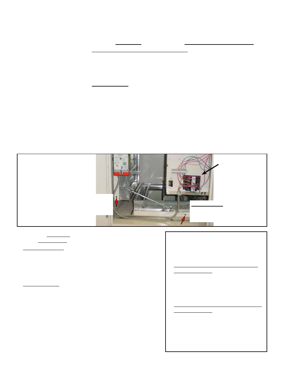
Options GE21 and GE22 - Drill a
5/8” hole in the outside air
damper mounting frame.
Option GE22 - Drill a
5/8” hole in the return air
damper mounting frame.
Economizer
Logic Module,
P/N 220637
FIGURE 24A - Mixing Box
with Optional Economizer
Logic Module
3. Install the Return Air Enthalpy Sensor in the Return Air
Duct - Option GE22
a)
Attach the Sensor - On the same side as the electrical
box in the mixing box, position the sensor on the inside
of the return air duct. The sensor may be mounted in any
orientation but must be located so that it is exposed to freely
circulating air. Position the sensor in a central location on the
side of the duct and attach with the two screws provided.
b)
Wire the Sensor - Connect the two wires to the sensor as
shown on the wiring diagram. Drill a 5/8” hole in the return air
damper mounting frame as illustrated in
FIGURE 24A. Insert
the strain relief bushing. Bring the wires through the opening
and route them to the bottom of the electrical box. Use the
stick-on wire holders and the wire ties to prevent the wires
from interfering with the damper operation. Insert a strain
relief bushing in a hole in the bottom of the electrical box and
route the wires through. Make connections at the economizer
logic module as shown on the wiring diagram.
Installation of Option GE22 control is complete. Refer to
FIG-
URES 24B and 24C to set the economizer logic module.
Operating Sequence with Economizer
Option
On a call for low stage cooling
1. The blower motor is energized.
2. With the outdoor enthalpy less than the
return air enthalpy:
a) The stage 1 and 2 cool circuits are locked
out.
b) Dampers are positioned by the
economizer and mixed air sensor.
3. With outdoor air enthalpy higher than the
return air enthalpy:
a) The stage 1 cool circuit is energized.
b) Dampers are positioned for minimum
outside air.
c) On a call for high stage cooling, the stage
2 and 3 circuits are staged appropriately.
6.0 Mechanical
(cont’d)
6.4 Unit Inlet Air (cont’d)
6.4.5.3 Mixing Box Damper and Control Options
(cont’d)