0 mechanical (cont’d), Table 10b - sizing gas supply lines, 2 checking burner gas pressure – Reznor RXH (Outdoor PreevA) Unit Installation Manual User Manual
Page 16: Table 10a - gas connection sizes, Figure 10 - gas connection, 1 gas supply and connections (cont’d)
Form I-RDH/REH/RHH/RXH (12-14), Page 16
Capacity of Piping -
Cubic Feet per Hour based on 0.3” w.c. Pressure Drop
Specific Gravity for Natural Gas -- 0.6 (Natural Gas -- 1000 BTU/Cubic Ft)
Specific Gravity for Propane Gas -- 1.6 (Propane Gas -- 2550 BTU/Cubic Ft)
Length of
Pipe
Diameter of Pipe
1/2”
3/4”
1”
1-1/4”
1-1/2”
2”
Natural Propane Natural Propane Natural Propane Natural Propane Natural Propane Natural Propane
20’
92
56
190
116
350
214
730
445
1100
671
2100
1281
30’
73
45
152
93
285
174
590
360
890
543
1650
1007
40’
63
38
130
79
245
149
500
305
760
464
1450
885
50’
56
34
115
70
215
131
440
268
670
409
1270
775
60’
50
31
105
64
195
119
400
244
610
372
1105
674
70’
46
28
96
59
180
110
370
226
560
342
1050
641
80’
43
26
90
55
170
104
350
214
530
323
990
604
90’
40
24
84
51
160
98
320
195
490
299
930
567
100’
38
23
79
48
150
92
305
186
460
281
870
531
125’
34
21
72
44
130
79
275
168
410
250
780
476
150’
31
19
64
39
120
73
250
153
380
232
710
433
175’
28
17
59
36
110
67
225
137
350
214
650
397
200’
26
16
55
34
100
61
210
128
320
195
610
372
Note: When sizing supply lines, consider possibilities of future expansion and increased requirements.
Refer to National Fuel Gas Code for additional information on line sizing.
TABLE 10B - Sizing Gas
Supply Lines
Inlet Pressure (applies to all gas controls)
Before attempting to measure or adjust valve outlet gas pressure, the inlet (supply)
pressure must be within the specified range both when the heater is in operation and
on standby. Incorrect inlet (supply) pressure could cause excessive outlet gas pres-
sure immediately or at some future time. If natural gas inlet (supply) pressure is too
high, install a regulator in the supply line before it reaches the heater. If natural gas
supply pressure is too low, contact your gas supplier.
Inlet pressure to the valve for natural gas must be a minimum of 5” w.c. or as noted
on the rating plate and a maximum of 14” w.c. Inlet supply pressure to the valve for
propane gas must be a minimum of 11” w.c. and a maximum of 14” w.c.
Manifold Pressure at the Burner Orifice
Measuring manifold gas pressure cannot be done until the heater is in operation. It is
included in the “Check After Startup” steps, Paragraph 9.3. The procedure required
depends on the type of gas control option:
• Single and Two Stage Options
AG1, AG2, AG3, AG15, AG16, AG60, AG61,
AG62, DG1, DG5, D12C - Follow INSTRUCTIONS starting below;.
• Electronic Modulation (2:1 turndown) Options.AG8, AG9, AG9H - Follow
instructions on pages 17-18.
• Electronic Modulation (4:1 turndown) Options.AG40, DG2, DG6, D12B -
Follow instructions on pages 17-18.
• Electronic Modulation (8:1 turndown) Options AG58, D12G - Follow
instructions on pages 18-19.
All gas pressure measurements should be done with a manometer (fluid-filled gauge)
rather than a spring type gauge due to the difficulty of maintaining calibration. Use a
water column manometer readable to the nearest tenth of an inch.
6.1.2 Checking Burner
Gas Pressure
NOTE: If unsure of the
Gas Control Option Code
(AG1, AG2, AG3, AG8,
AG9, AG9H, AG15, AG16,
AG40, AG58, AG60, AG61,
AG62, DG1, DG2, DG5,
DG6, D12B, D12C, or
D12G), check the wiring
diagram on the heater. All
option codes affected by
electrical power are listed
on the bottom of the wir-
ing diagram after the unit
Model and Size.
6.0 Mechanical
(cont’d)
6.1 Gas Piping and Pressures - Models RDH and RHH (cont’d)
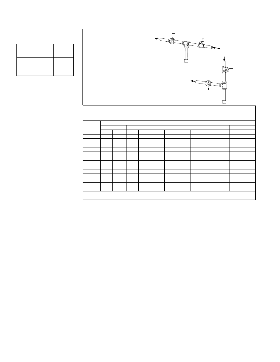
TABLE 10A - Gas
Connection Sizes
From Gas Supply
(horizontal or vertical)
Manual
shutoff
Drip
Leg
*To Gas
Valve
(inside the
cabinet)
*To Gas
Valve
(inside the
cabinet)
Ground
Joint
Union
Drip
Leg
Ground Joint Union
Manual shutoff
FIGURE 10 -
Gas
Connection
*See gas connection
location on dimension
drawing, page 7 or
page 9.
6.1.1 Gas Supply and Connections (cont’d)
RDH
75, 100,
125, 150,
175, 200
225, 250,
300, 350.
400A
RHH
130 & 180 260 & 350
Natural
Gas
1/2”
3/4”
Propane
1/2”
3/4”
NOTE: These are
not supply line sizes.