Reznor RXH (Outdoor PreevA) Unit Installation Manual User Manual
Page 33
Form I-RDH/REH/RHH/RXH (12-14), P/N 215210 R14, Page 33
Evaporative
Cooling
Module
(factory attached)
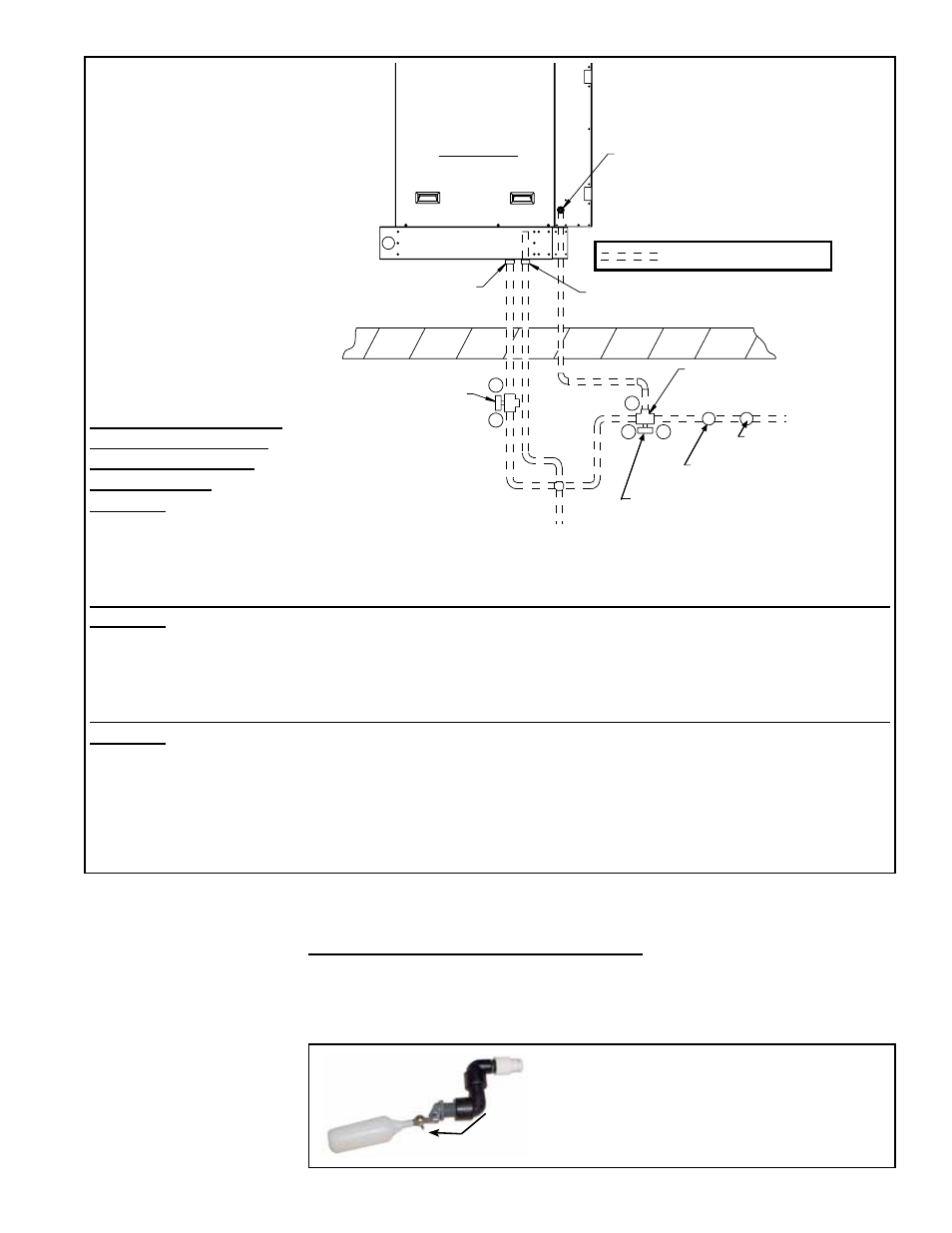
Inlet Water Connection
(1/2 male NPT fitting)
Overflow Fitting
3/4 male NPT tapped
with 1/2 female NPT
Drain Fitting
3/4 male NPT tapped
with 1/2 female NPT
2-Way Solenoid Valve
(normally open)
1/2 female NPT
(A 2-way valve is in
Options CT1, CT2, and CT3.
Option CT6 requires
Option CT1, CT2, or CT3.)
To Drain
3-Way Solenoid Valve (valve is suitable for
a maximum close-off pressure differential
of 25 psi and a system static pressure of 300
psi) - 1/2 NPT, 2-position spring return
(normally closed at B port)
(A 3-way valve is in Options CT1, CT2, CT3,
and CT5. Option CT6 requires Option CT1,
CT2, or CT3.)
Actuator must be above the
valve body when mounted
in horizontal piping.
Roof
Water Inlet
Field-supplied
Service Valve
Field-supplied Pressure
Regulator (if required)
A
A
B
B
C
= Field-installed Water Piping
Left Side View
FIGURE 26 - Field-installed
optional Fill and Drain
Valves for Pump and Float
System (Option CT1, CT2, or
CT3)
and
Freeze Protection Kits
(Option CT5 for AquaSaver
and Option CT6 for Pump
and Float System)
Sequence of Operation
with Optional Fill and
Drain and/or Freeze
Protection Kits
Applies to: Float and Pump System with Optional
Fill and Drain Kit (Option CT1, CT2, or CT3)
1) Call for cooling.
2) 2-way valve is energized and closes B to A.
3) 3-way valve is energized opening B to C and closing A to C.
4) During no call for cooling, valves return to normal state.
Applies to: AquaSaver Timed Water System with Optional Freeze Protection (Option CT5)
1) Call for cooling.
2) 3-way valve is energized opening B to C and closing A to C.
3) If outside air temperature drops below freeze protection controller setting, 3-way valve is de-energized and
AquaSaver 24V solenoid valve remains energized for eight minutes to allow complete system water drainage.
4) During no call for cooling, 3-way valve returns to normal state.
Applies to: Float and Pump System with Optional Fill and Drain Kit (Option CT1, CT2, or CT3) and Freeze
Protection (Option CT6)
1) Call for cooling.
2) 2-way valve is energized and closes B to A.
3) 3-way valve is energized opening B to C and closing A to C.
4) If outside air temperature drops below freeze protection controller setting, valves return to normal state.
5) During no call for cooling, valves return to normal state.
tion (above 32°F), either horizontal or vertical, in line with and as close to the solenoid
valve as possible. Follow the manufacturer’s instructions to install and maintain the
water hammer arrestor.
Recirculating Float and Pump Control System - Turn on the water supply and check
for good flow. When the float valve (
FIGURE 27) shuts off the water supply, measure
the water depth. The depth of the water should be approximately 3” (76mm). If neces-
sary, adjust the position of the float valve with the wing nut to obtain the proper water
level.
Adjust the float valve position with the wing nut to
maintain approximately 3” (76mm) of water in the
reservoir
.
1/2” MPT Water Supply Connection
FIGURE 27 - Float
Valve, P/N 216553