5 electrical operating components, Cl33, Cl52 – Reznor RXH (Outdoor PreevA) Unit Installation Manual User Manual
Page 46: Cl22, Cl36, Cl23, 0 electrical (cont’d), 4 control wiring (cont’d), 1 high temperature limit control - rdh/rhh, Rdh & rhh w/ag58)
Form I-RDH/REH/RHH/RXH (12-14), Page 46
If using an analog control system, use either an optional or a field-provided low-voltage
(24V) thermostat. (A thermostat is not supplied.) Install the thermostat according to the
manufacturer’s instructions. Depending on the control system option, select either a
single-stage or two-stage thermostat.
Analog Control System
Requires an Optional
or Field-Supplied
Thermostat
FIGURE 41 - 24V Single-Stage and Two-Stage Thermostat Wiring
NOTES:
1) JUMPER THERMOSTAT TERMINALS RH TO RC.
FIELD WIRING
(USE
WITH AG2)
TWO ST
AGE HEA
T/COOL
THERMOST
AT W/F
AN SWITCH
(SEE NOTE #1)
G
W1
W2
Y2
Y1
RC
RH
RH
(SEE NOTE #1)
A1
G
W2
W1
Y2
Y1
X
A2
RC
G
W2
W1
Y2
Y1
C
R
TERMINAL
STRIP
G
W1
W2
Y2
Y1
C
R
TERMINAL
STRIP
CL33
P/N 221038
CL52
P/N 220632
CL22
P/N 220630
CL22
P/N 220630
SINGLE ST
AGE THERMOST
AT
TERMINAL
STRIP
G
W2
W
W1
Y2
Y1
C
R
R
CL1
P/N 255350
W2
TWO ST
AGE HEA
T/COOL
THERMOST
AT W/F
AN SWITCH
TERMINAL
STRIP
G
W2
G
Y1
(SEE NOTES #1
AND #2)
W1
Y2
W1
Y2
RC
RH
Y1
C
R
(RECIRCULATING AIR) (MAKE-UP AIR)
14
IN HEAT
SECTION
TERMINAL
BLOCK
G
W
Y
R
RC
(SEE NOTE #1)
G
W1
W2
Y2
Y1
C
TERMINAL
STRIP
R
SINGLE ST
AGE PROGRAMMABLE THERMOST
AT
TWO ST
AGE PROGRAMMABLE THERMOST
AT
C
C
2) SET FAN CONTROL FUNCTION TO "ELECTRIC FURNACE".
BK
(Ref WD 226260)
CL36
(RDH & RHH
w/AG58)
P/N 257600
CL23
(RDH & RHH)
P/N 257338
IN HEAT
SECTION
TERMINAL
BLOCK
W2
TWO ST
AGE HEA
T/COOL
PROGRAMMABLE THERMOST
AT
TERMINAL
STRIP
G
W2
G
Y
W
Y2
W1
Y2
RC
R
Y1
C
R
14
C
BK
S2
S1
A
Y1
Y2
G
W1
R
W2
C
THERMOSTAT
TERMINAL STRIP
(NOT IN
SEQUENCE)
X
RC
RH
W1
G
MX
MH
AS
AS
DISCHARGE
AIR SENSOR
Y1
(USE WITH
AG3,15,16,60,61,62)
PROGRAMMABLE MODULA
TING HEA
TING/COOLING
THERMOST
AT
(SEE NOTE #1.)
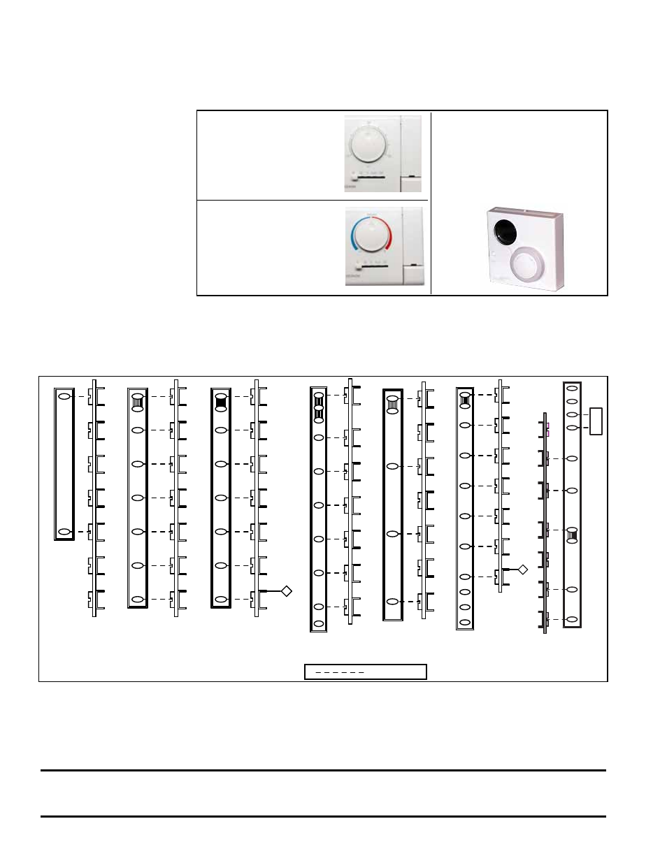
If ordered with an optional expansion card, a digital control system will provide week-
day and weekend scheduling of start/stop operation or interface to a field-supplied
Johnson N2 or Lonmark building automation system.
See the control instruction manual for additional information.
FIGURE 40A - Room
Command Module, P/N
211423, Sensing Space
Temperature for Digital
Controls, Option DG1
and DG2
FIGURE 40B - Room
Command Module,
P/N 211424, Sensing
Discharge Temperature
for Digital Controls,
Option DG5 and DG6
FIGURE 40C - Room
Command Module, Option
CL67, P/N 260599 Sensing
Discharge Temperature for
Digital Controls, Options
D12B, D12C, D12D, D12E,
D12G
All units are equipped with a temperature activated auto reset capillary-type limit con-
trol. The control is factory set and is non-adjustable. If the setpoint is reached, the limit
control will interrupt the electric supply to the gas valve. This safety device provides
protection in the case of motor failure or lack of airflow due to a restriction at the inlet
or outlet.
7.5.1 High Temperature Limit Control - RDH/RHH
7.5 Electrical
Operating
Components
CAUTION: The auto reset limit control will continue to shut down the heater until the cause
is corrected. Never bypass the limit control; hazardous conditions could result. See Hazard
Intensity Levels, page 2.
7.0 Electrical
(cont’d)
7.4 Control Wiring
(cont’d)
7.4.2 Analog or Digital
Controls (cont’d)
Digital Control Systems (cont’d)