0 mechanical (cont’d), 4 unit inlet air (cont’d), Step 3 - install louver rack – Reznor RXH (Outdoor PreevA) Unit Installation Manual User Manual
Page 26: Step 4 - install screen, 4 optional filter rack and filters, Table 16 - filter quantity and sizes, 1 mixing box configurations, Table 17 - inlet air filter pressure drops, 3 screened outside air hood, option as2 (cont’d)
Form I-RDH/REH/RHH/RXH (12-14), Page 26
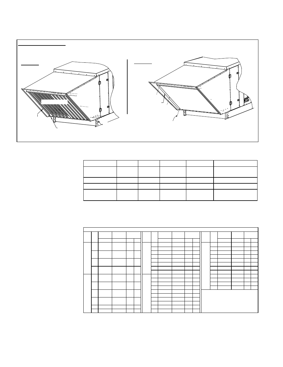
STEP 3 - Install
louver rack.
Screen
Retainer
(part of
assembled
louver rack)
3a) Position the
louver rack in
the hood opening.
3b) Attach the louver
rack as shown with
sheetmetal screws.
Repeat on the other side.
STEP 4 - Install
screen.
4b) Attach screen clamp with three sheet-
metal screws. Repeat procedure on the
other side to install second screen clamp.
Outside air hood installation is complete.
Louver Rack
4a) Position
the screen and
the screen clamp.
Screen
INSTALLATION NOTE: If the installation includes damper control Option GE21 or GE22 that requires field installation
of a sensor in the outside air inlet, attach the sensor and connect the wires
before STEP 3 below. See Instructions on
page 29.
Filter rack and filters are factory-installed optional equipment. Depending on which
option was ordered, filters may be 2” disposable, 2” or 4” pleated disposable, or 2”
permanent.
6.4.4 Optional Filter
Rack and Filters
RDH Sizes
75, 100
125, 150 175, 200, 225
250, 300
350, 400A
REH Sizes
10A, 20A,
40A
15B, 30B,
60B
N/A
30D, 60D,
90D, 120D
40E, 80E, 120E
RHH Sizes
N/A
N/A
130, 180
260
350
RXH Sizes
000A
000B
000C
000D
000E
Filters - (Qty)
W x H in inches
(2)
16 x 25
(2)
20 x 25
(2) 16 x 16;
(2) 16 x 20
(3) 16 x 16;
(3) 16 x 20
(1) 16 x 16; (2) 20 x 20;
(3) 16 x 20
TABLE 16 - Filter
Quantity and Sizes
(Quantity and width and
height dimensions apply
to all type and thickness of
filters.)
6.4.5 Optional Mixing
Box (factory-installed) -
RDH, REH, RXH
If installation includes an Option MXB1 mixing box, it is factory installed in one of the
configurations illustrated in
FIGURE 20.
6.4.5.1 Mixing Box Configurations
All mixing box inlet air openings have a duct flange. (See dimensions in
FIGURE 22.)
All inlet air ducts should be attached and sealed. Return air duct must have a free area
equal to the return duct connection. See mixing box configurations in
FIGURE 20.
TABLE 17 - Inlet Air
Filter Pressure Drops
Pressure Drops for Clean Factory-Installed Filters by Type and Size ("w.c.)
Size CFM
Disposable Permanent
Aluminum
Pleated
Disposable
Size
CFM
Disposable Permanent
Aluminum
Pleated
Disposable
Size
CFM
Disposable Permanent
Aluminum
Pleated
Disposable
2''
2''
2''
4''
2''
2''
2''
4''
2''
2''
2''
4''
RDH
75,
100;
REH
10A,
20A,
40A;
RXH
000A
569
0.0
0.0
0.0
0.0
RDH
175,
200,
225;
RHH
130,
180;
RXH
000C
1329
.1
0.0
.1
0.0
RDH
350,
400A;
REH
40E,
80E,
120E;
RHH
350;
RXH
000E
2657
.1
0.0
.1
0.0
1650
.1
0.0
.1
0.0
3300
.1
0.0
.1
0.0
1000
.1
0.0
.1
0.0
2000
.1
0.0
.1
.1
3500
.1
0.0
.1
.1
2500
.1
.1
.1
.1
4000
.1
0.0
.1
.1
1500
.1
0.0
.1
.1
3000
.1
.1
.2
.1
4500
.1
.1
.1
.1
3500
.2
.1
.2
.2
5000
.1
.1
.2
.1
1898
.1
.1
.2
.1
4000
.2
.1
.3
.2
5500
.2
.1
.2
.1
4271
.2
.1
.3
.2
6000
.2
.1
.2
.1
RDH
125,
150;
REH
15B,
30B,
60B;
RXH
000B
949
0.0
0.0
0.0
0.0
RDH
250,
300;
REH
30D,
60D,
90D,
120D;
RHH
260;
RXH
000D
1898
.1
0.0
.1
0.0
6500
.2
.1
.2
.2
2050
.1
0.0
.1
0.0
7000
.2
.1
.3
.2
1250
.1
0.0
.1
0.0
2500
.1
0.0
.1
0.0
7400
.2
.1
.3
.2
3000
.1
0.0
.1
.1
7593
.3
.1
.3
.2
1500
.1
0.0
.1
0.0
3500
.1
0.0
.1
.1
4000
.1
.1
.1
.1
2000
.1
0.0
.1
.1
4500
.1
.1
.2
.1
5000
.2
.1
.2
.1
2500
.1
.1
.2
.1
5500
.2
.1
.2
.2
2847
.2
.1
.2
.1
5694
.2
.1
.3
.2
6.0 Mechanical
(cont’d)
6.4 Unit Inlet Air (cont’d)
6.4.3 Screened Outside Air Hood, Option AS2 (cont’d)
If the system does not have an optional cooling coil module, the vertical filter rack is
located in the entering air side of the blower cabinet. If the system has an optional
draw-through cooling coil module, the filter rack is located in the entering air side of
the cooling coil module.
FIGURE 19B - Outside Air Hood Assembly STEPS (cont’d)