8 unit discharge - rdh, reh, rhh, and rxh, 0 mechanical (cont’d) – Reznor RXH (Outdoor PreevA) Unit Installation Manual User Manual
Page 38
Form I-RDH/REH/RHH/RXH (12-14), Page 38
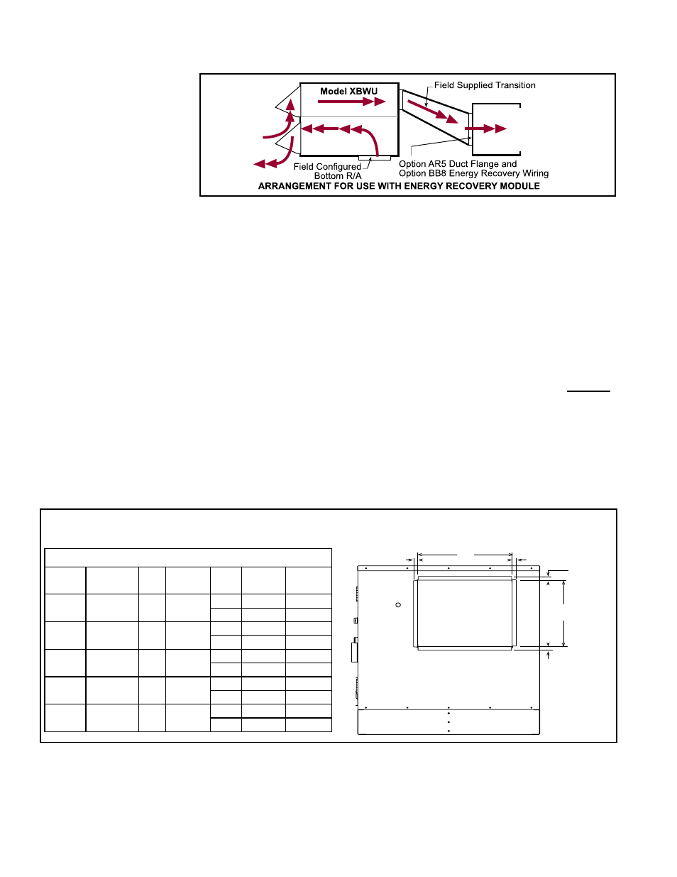
FIGURE 34 - Field-
installed Optional
Energy Recovery
Module, Option XBWU
Model
RDH, REH,
RHH, or
RXH
6.8 Unit Discharge -
RDH, REH, RHH,
and RXH
Depending on which model and which options were ordered, there is a horizontal open-
ing with no duct flange (RDH, RHH, or RXH), a horizontal opening with a duct flange
(RDH, RHH, RXH, or REH), or a downturn plenum with bottom opening with a duct
flange with or without dampers (RDH, RHH, RXH, or REH). Model REH units are for
ducted systems only and require a factory-installed duct flange or a downturn plenum.
6.8.1 Optional Downturn Plenum (factory-installed)
If ordered with a downturn plenum, the unit has a bottom opening with a duct flange.
See the opening dimensions in
FIGURE 4, page 9. See FIGURE 8, page 12, for the
opening dimensions in relation to an optional roof curb.
If ordered with a damper, the damper closes the discharge opening when the unit is
not operating.
6.8.2 Horizontal Discharge Duct Flange for REH, RDH, and RXH without
a hot water heat module
Dimensions for attaching ductwork are shown below in
FIGURE 35. The discharge
duct flange extends horizontally 4” (102mm) from the end of the cabinet and has a
3/4” (19mm) wide flange on all sides. Requirements and recommendations are listed
in Paragraph 6.8.4 for sizing and attaching ductwork.
NOTE: Model REH with horizontal discharge always has a factory-installed duct
flange. Duct flange is optional on Models RDH, RHH, and RXH.
X
Y
3/4(19mm)
3/4(19mm)
3/4
(19mm)
3/4
(19mm)
Discharge
Opening
with Duct
Flange
Option AX4
TABLE 24 - Dimensions of Discharge Duct Flange
RDH
REH
RHH RXH (no
heat)
X
Y
75, 100 10A, 20A,
40A
N/A
000A
inches 17-9/16
13-9/16
mm
446
345
125, 150 15B, 30B,
60B
N/A
000B
inches 27-9/16
13-9/16
mm
700
345
175,
200, 225
N/A
130,
180
000C
inches 20-3/4
22-13/16
mm
527
580
250, 300 30D, 60D,
90D, 120D
260
000D
inches 28-5/8
22-13/16
mm
727
580
350,
400A
40E, 80E,
120E
350
000E
inches 38-5/16 22-13/16
mm
973
580
FIGURE 35 - Dimensions of Horizontal Discharge Duct Flange on REH, RDH, RHH,& RXH without a
hot water heat module (For RXH with a hot water heat module, see Paragraph 6.8.3.)
6.8.3 Hot Water Heat
Module - RXH Only
The optional hot water heat module is factory-installed on the unit base at the dis-
charge end of a Model RXH. The module was either ordered with a factory-installed
coil or the coil is field-supplied for installation at the job site. Controls are field supplied.
Dimensions - The cabinet height and width are the same as the RXH; see Paragraph
4.2. See
FIGURE 36A for length and water connection dimensions. For system length,
add the length of the module to the RXH length in Paragraph 4.2.
6.0 Mechanical
(cont’d)
6.7 Optional Energy Recovery Module (field-installed) - RDH, REH,
RHH, and RXH (cont’d)