Reznor RXH (Outdoor PreevA) Unit Installation Manual User Manual
Page 49
Form I-RDH/REH/RHH/RXH (12-14), P/N 215210 R14, Page 49
Compressor
Model
ARI
Tonnage
208/240 V 1 PH 208/240 V 3 PH 460 V3 PH 575 V3 PH
RLA
LRA
RLA
LRA
RLA LRA RLA LRA
ZP29K5
2.4
14.1
77.0
9.0
71.0
5.6
38.0
3.8
36.5
ZP57K3
4.8
30.1
158.0
20.5
155.0
9.6
75.0
7.6
54.0
TABLE 32 - Reheat Compressor
Compressor
- Reheat
circuit is
charged at
the factory
with R410A
Refrigerant
7.6.2 Reheat Module
(Options AU7L and
AU7R) Compressor -
RDH, REH, RHH, RXH
The compressor in the optional reheat module is a high efficiency hermetic scroll type
that is factory charged with R410A refrigerant. The compressor has a low pressure
cutoff (LPCO) switch for protection against damage due to a loss of charge. This pro-
tection prevents short cycling on the internal overload (IOL) which can pump the oil
out of the compressor. The compressor also has a manual reset high pressure cutout
(HPCO).
NOTE: See Operation/Maintenance Form O-PREEVA (in the Literature Bag), for
additional information on compressor maintenance and R410A refrigerant.
IMPORTANT: Do not release refrigerant to the atmosphere! If required service procedures
include the adding or removing of refrigerant, the service technician must comply with
all federal, state and local laws. The procedures discussed in this manual should only be
performed by a qualified HVAC technician.
DANGER
This reheat circuit contains R410A high pressure refrigerant. Hazards exist that could
result in personal injury or death. Installation, maintenance, and service should only be
performed by an HVAC technician qualified in R410A refrigerant and using proper tools and
equipment. DO NOT USE service equipment or tools designed for R22 refrigerant.
7.6.3 Remote Console
for Controls - RDH,
REH, RHH, RXH
If the system includes an optional control console, it is shipped separately for field
installation. A selection of remote consoles is available with a variety of combinations
of factory-mounted controls. All consoles include burner and blower indicator lights
and may include a dirty filter indicator light (see below); a cooling on indicator light;
an on/off switch; a summer/winter/off control switch; a heat/vent/cool system switch;
and/or a potentiometer for damper control. The thermostat or room command module
may also be mounted on the console. Depending on the console selected, it may be
10-3/4” (273mm) or 15-3/4” (400mm) in length. All consoles are 7-5/8” (194mm) high
and 2-5/8” (67mm) deep. Consoles may be flush or recess mounted. If recessing (not
using the mount ring) subtract 7/8” (22mm) from the height and width.
Wire the controls on the remote console according to the wiring diagram. Refer to
TABLE 28 on page 45 for minimum control wire gauge by length.
Dirty Filter Switch - If there is a dirty filter indicator light on the console, there is a dirty
filter switch in the unit. After the unit is started, before continuous operation, the dirty
filter switch must be set.
Modulating Reheat,
Option AUR1
With modulating reheat, a sensor monitors the air temperature as it leaves the reheat
coil. Based on a potentiometer setpoint and the sensor signal, the board will open or
close a refrigerant bypass valve. Changing the amount of refrigerant hot gas being
added to the refrigerant liquid before it enters the pre-cool coil will “modulate” the func-
tion of the pre-cool and reheat coils to provide the desired leaving air temperature.
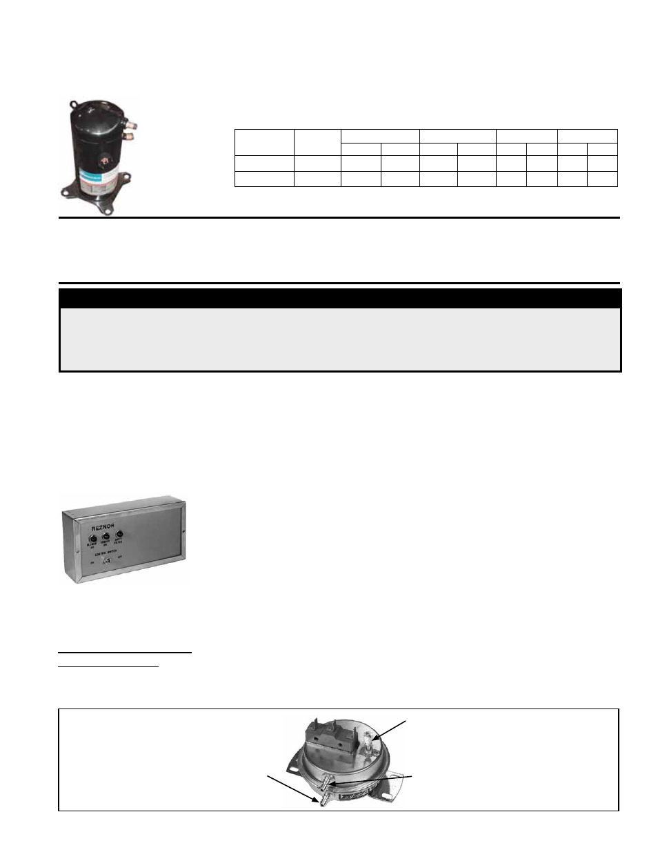
FIGURE 43 - Dirty Filter Switch,
P/N 105507 (must be set prior to
continuous operation)
Set screw (on front of switch)
must be manually adjusted after
the system is in operation.
Negative pressure connection is
toward the “front or top” of the
switch (senses blower side of filters)
Positive pressure connection is
toward the “back or bottom” of the
switch (senses air inlet side of filters)
Instructions for Setting
Dirty Filter Switch
(FIGURE 43)
With clean filters in place; all doors closed (except electrical compartment); and the
blower opening, increase the pressure setting by adjusting the setscrew on the switch
clockwise until the filter light is energized or the screw is bottomed out. At that point,
adjust the setscrew three full turns counter clockwise or until the screw is top ended.
At that setpoint, the filter light will be activated at approximately 50% filter blockage.