2 clearances, 0 suspension and mounting, 1 weights – Reznor RPBL Unit Installation Manual User Manual
Page 8: 2 suspension - model sscbl, 3 indoor mounting on field-supplied supports, 0 dimensions and clearances (cont'd)
Form I-SSCBL/RPBL, Page 8
4.2 Clearances
For safety and convenience, provide clearances as shown in the table. Clearance to
combustibles is defined as the minimum distance from the heater to a surface or object
that is necessary to ensure that a surface temperature of 90°F above the surround-
ing ambient temperature is not exceeded. Minimum clearances are also listed on the
heater rating plate.
Required
Clearances -
inches (mm)
Model
SSCBL
Side Opposite Controls - 6" (152mm) is required for clearance to combustibles.
30" (762mm) service clearance is recommended for access to the motor.
Control Side (for service) - 56" (1422mm)
Top - 6" (152mm)
Furnace Bottom - 6" (152mm)
Model
RPBL
Control Side (for service) - 56" (1422mm)
Side Opposite Controls - 30" (762mm) service clearance is recommended for access
to the motor.
*Furnace Bottom - 0" (0mm)
*When installed on a roof curb on a combustible roof, the roof area enclosed within the curb must be either
ventilated, left open, or covered with non-combustible material which has an "R" value of at least 5.0. See
FIGURE
9A, page 11.
5.0 Suspension
and Mounting
5.1 Weights
Before installing, check the supporting structure to be sure that it has sufficient load-
carrying capacity to support the weight of the unit. Properly suspending or mounting
the unit is the responsibility of the installer. Model SSCBL systems are designed for
either suspension or mounting. Model RPBL systems are designed for mounting only.
All installed systems must be level.
Model and
Size
Net Weight (lbs and kg)
400
500
600
700
800
1050
1200
SSCBL lbs
849
1104
1104
1184
1245
1476
1565
kg
385
500
500
537
565
670
710
RPBL
lbs
849
1104
1104
1184
1245
1476
1565
kg
385
500
500
537
565
670
710
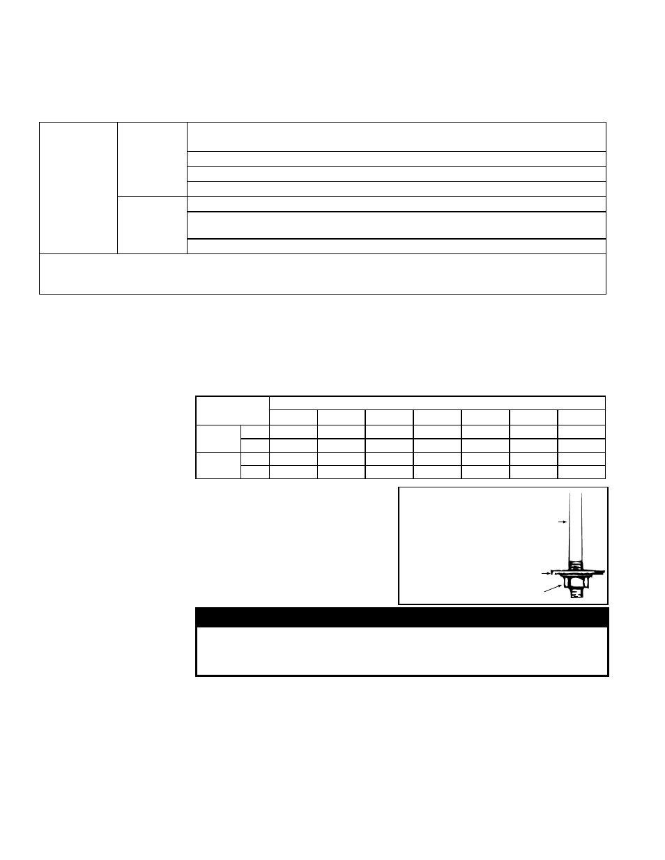
A Model SSCBL unit is equipped with a
load-bearing curb cap which forms an
integral part of the unit. The curb cap is
welded at all joints and has suspension
holes at each corner and hanger brack-
ets on the sides. See
FIGURE 2 for sus-
pension dimensions. Each suspension
location requires a 1/2" threaded rod as
illustrated in
FIGURE 5.
5.3 Indoor
Mounting on
Field-Supplied
Supports -
Model SSCBL
Prior to installation, be sure that the method of support is in agreement with all local
building codes. Whether the supports are being mounted directly on a surface or being
placed "up" on additional structure, the horizontal length of the system should be sup-
ported by two 4x4 treated wooden rails. Cut the rails to the appropriate length (Dimen-
sion "A" in
FIGURE 6A).
Space the 4x4 wooden rails (See "B" Dimension,
FIGURE 6A) so that the curb cap
"skirt" will fit over the edge of the boards with the rails setting inside the horizontal
length of the curb cap.
If the rails are being laid directly on a surface, position them as shown in
FIGURE 6B.
Set the system on the rails, leaving the "ends" underneath open for ventilation.
1/2
Threaded
Rod
Lockwasher
1/2-13 Nut
FIGURE 5 - Support
Rod Detail -
Required at all
Suspension
Points
4.0 Dimensions
and Clearances
(cont'd)
5.2 Suspension -
Model SSCBL
WARNING
Units must be supported level for proper operation. Do not place
or add additional weight to the suspended unit. See Hazard Levels,
page 2.