Reznor RPBL Unit Installation Manual User Manual
Page 31
Form I-SSCBL/RPBL, P/N 149159 R7, Page 31
The optional dirty filter pressure switch is used to provide warning to the user by ener-
gizing an indicator light on an optional remote console. The light indicates that the
filters are in need of cleaning or changing. The adjustable, single-pole/normally open
differential switch closes when an increase in pressure differential above the setpoint,
is sensed across the filter bank.
This switch is located in the furnace section. See page 43,
FIGURE 46, Item 17. After
the unit is started, before continuous operation, the dirty filter switch must be set.
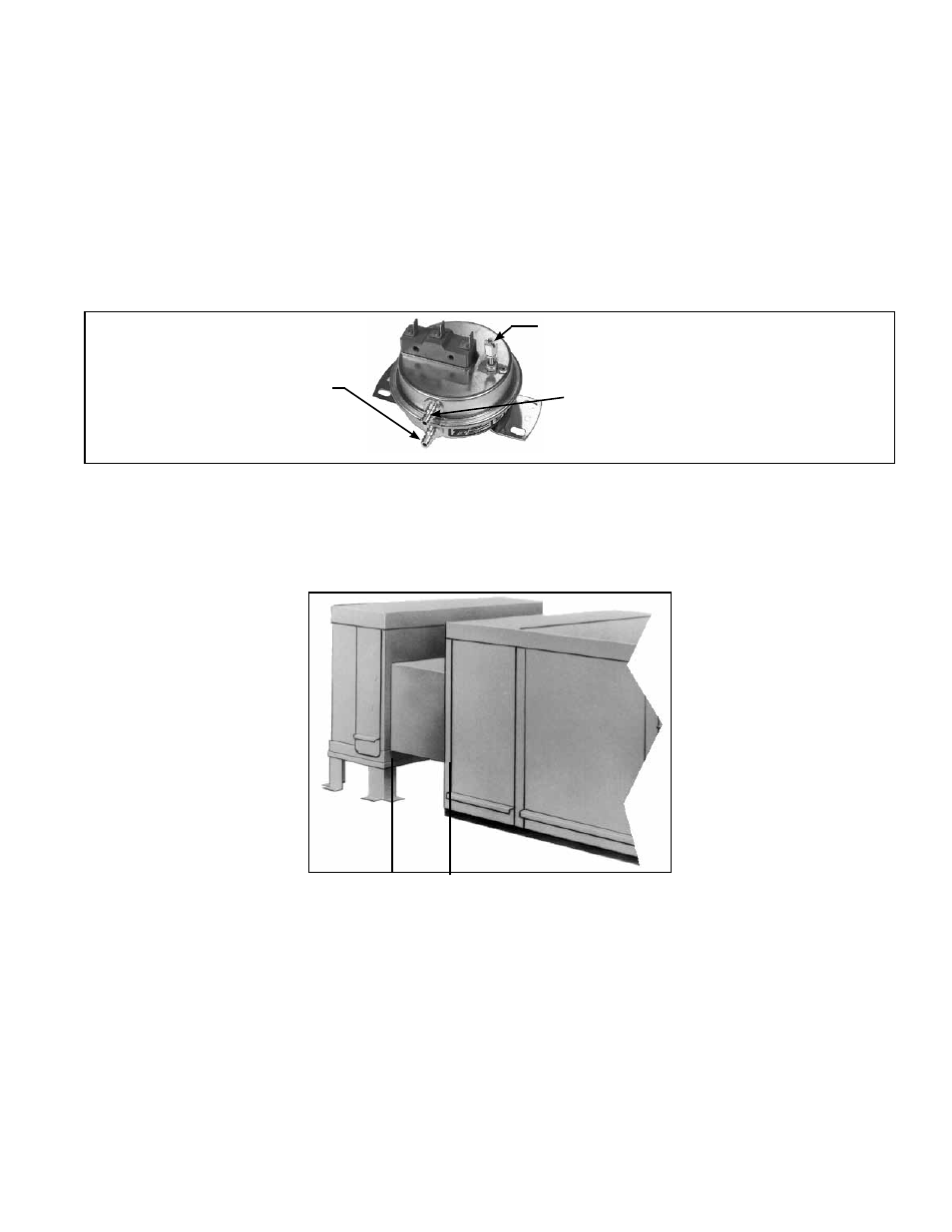
Instructions for Setting Dirty Filter Switch (FIGURE 33)
With clean filters in place, blower doors closed, and blower in operation, decrease the
pressure setting by adjusting the set screw on the switch clockwise until the filter light
is energized or the screw is bottomed out. At that point, adjust the set screw three full
turns counterclockwise or until the screw is top-ended. At that setpoint the filter light will
be activated at approximately 50% filter blockage.
FIGURE 33 - Dirty Filter
Switch
Set screw (on front of switch) must be
manually adjusted after the system is
in operation.
Negative pressure connection is
toward the "front" or "top" of the
switch (senses blower side of filters)
Positive pressure connection
is toward the "back" or
"bottom" of the switch
(senses air inlet side of filters)
6.3.5 Optional
Evaporative Cooling
Module - Applies to
Model RPBL
Blower Cabinet
Cooling
Module
and Base Connecting
Duct
FIGURE 34 - Optional
Evaporative Cooling
Module is factory-
assembled for field
attachment to the
blower cabinet (duct
and base are shipped
knocked down for field
assembly)
Evaporative cooling provides excellent comfort cooling at low initial equipment and
installation costs and low operating and maintenance costs. Direct evaporative cool-
ing works solely on the principle that water in direct contact with a moving airstream
will eventually evaporate if the droplets have long enough exposure. This evaporative
cooling module uses wetted rigid cellulose or glass fiber media to retain water in order
to allow time for evaporation.
The evaporative cooling module for these systems is factory assembled but is not
attached to the blower cabinet at the factory. It is shipped separately for field attach-
ment to the system blower cabinet. The base support for the cooling module and the
transitional ductwork between the cooling module and the blower cabinet inlet are
shipped separately and must be field assembled and installed. Complete installation
instructions including water and electrical connections are included with the evapora-
tive cooling module package.
Included in the cooling module installation booklet is a preparation checklist. All items
in that checklist should be consulted prior to beginning installation of the optional evap-
orative cooling module. Four of those items are listed below.
Make certain the supporting platform is capable of handling the additional load of a
full cooling module reservoir.
Weights of Evaporative Cooling Module - w/Wet Media & Full Reservoir (lbs.)
Module with 12" rigid cellulose media (Opt AS4) 431 lbs
Module with 12" rigid glass fiber media (Opt AS8) 514 lbs
Optional Dirty Filter
Switch