3 unit inlet air, 0 mechanical (cont'd) – Reznor RPBL Unit Installation Manual User Manual
Page 26
Form I-SSCBL/RPBL, Page 26
6.0 Mechanical
(cont'd)
6.3 Unit Inlet Air
6.2 Venting and Combustion Air (cont'd)
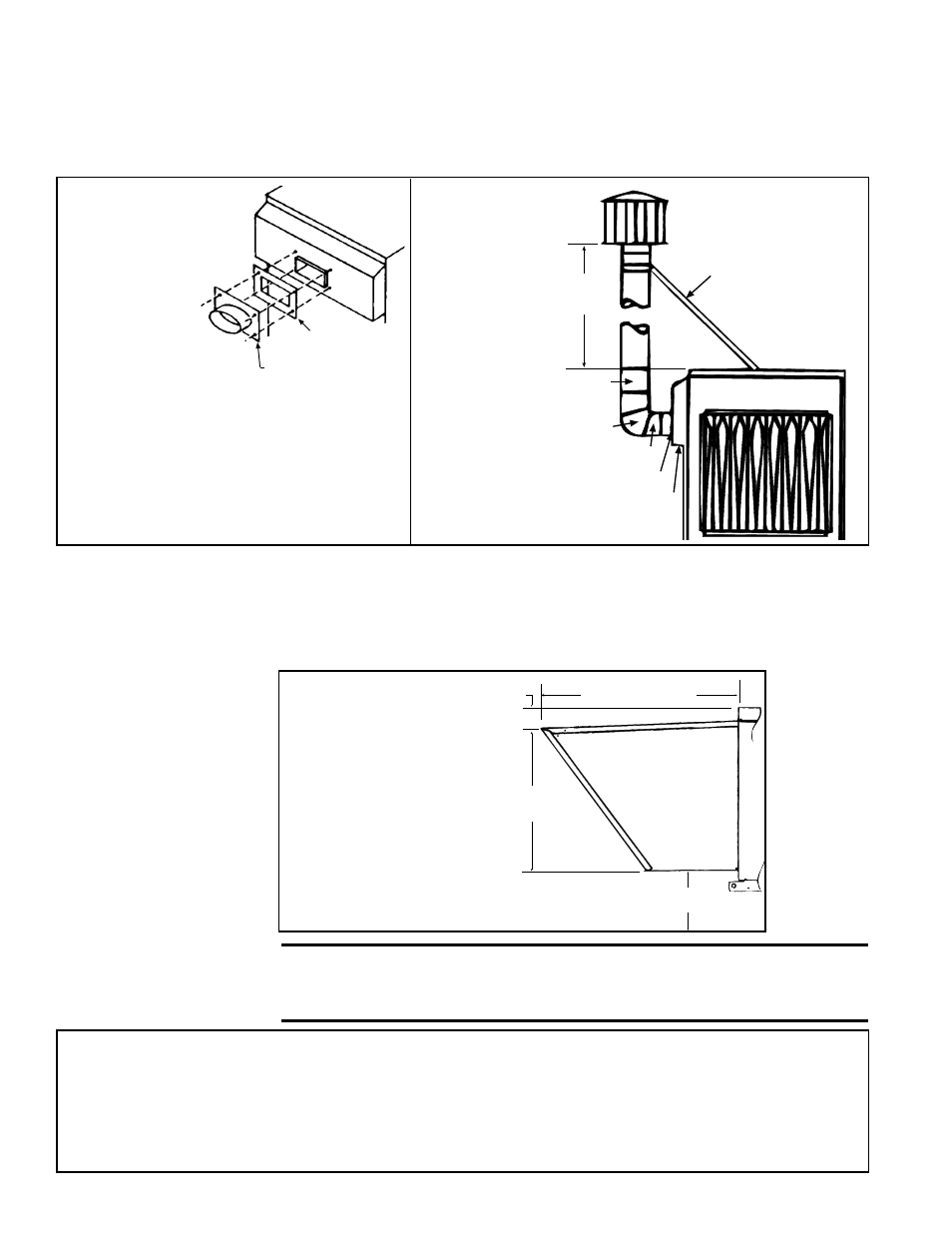
6.2.2 Venting Outdoor Power Vented Model RPBL (cont'd)
Vent Seal Plate,
P/N 43446
Oval Adapter Assembly,
P/N 103025
FIGURE 26A -
Installation
of Adapter
for Optional
Vertical Flue
Discharge
(Option CC3,
P/N 45021)
1) Remove and discard the louvered
discharge grill.
2) Using venter seal plate as a template, drill
holes. Use 3/8"-10 sheetmetal screws to
attach both the venter seal plate and the
oval adapter assembly.
5 Vent Cap,
P/N 110052
5 dia Flue Pipe
4
(1.2M)
5 dia
90° Elbow
18 (457mm) Straight Pipe
Oval Adapter Assy
Combustion Air Intake
Support angles for flue
pipe. Recommended
size is 1/2x1/2,
20 gauge
FIGURE 26B -
Installation of
the Vent Cap
(included in the
option package)
and the field-
supplied Piping
and Supports
Optional vertical vent piping provides compliance with local codes that require either
10-ft (3M) horizontal or 4-ft (1.2M) vertical clearance between the flue outlet and fresh
air intake of the heating system and/or the building.
6.3.1 100% Outside Air Hood - Model RPBL
Outside air hood (Option AS2) is a weatherized, screened hood designed to be field
assembled and installed around the horizontal inlet air opening of the blower cabinet.
The air hood includes a louver assembly designed to help eliminate moisture from the
inlet air. Complete installation instructions are packaged with the air hood option.
Optional
100%
Outside
Air Hood
43-17/32 (1106mm)
4-5/8
(117mm)
31-11/32
(796mm)
14 (356mm)
minimum
FIGURE 27 -
Dimensions of Outside
Air Hood, Option AS2
The width of the outside
air hood is the same as
the width of a blower
cabinet.
NOTE: Either a
manufacturer designed
optional air inlet hood as
shown in
FIGURE 27 or
an evaporative cooling
module as shown in
Paragraph 6.3.3 is required
to ensure complete weather
resistance.
Installation Instructions - 100% Outside Air Hood
Refer to
FIGURE 28. All screw ends except those across the bottom should be inside the air hood.
To avoid possible damage, it is recommended that the outside air hood be installed after the system has been placed
on the roof. The air hood should be installed before the heater is operated. Do not install the hood while the system
(furnace or blower) is in operation.
1. Top Panel -- On the air inlet side of the blower cabinet, remove the factory-installed screws attaching the blower
cabinet top. Slide the air hood top panel underneath the edge of the blower cabinet top.
The edge of the air
CAUTION: It is recommended that the inlet to the outside air hood NOT
be facing into the prevailing wind. Allow 14" minimum clearance from
the bottom of the air hood to the mounting surface.