Reznor RPBL Unit Installation Manual User Manual
Page 21
Form I-SSCBL/RPBL, P/N 149159 R7, Page 21
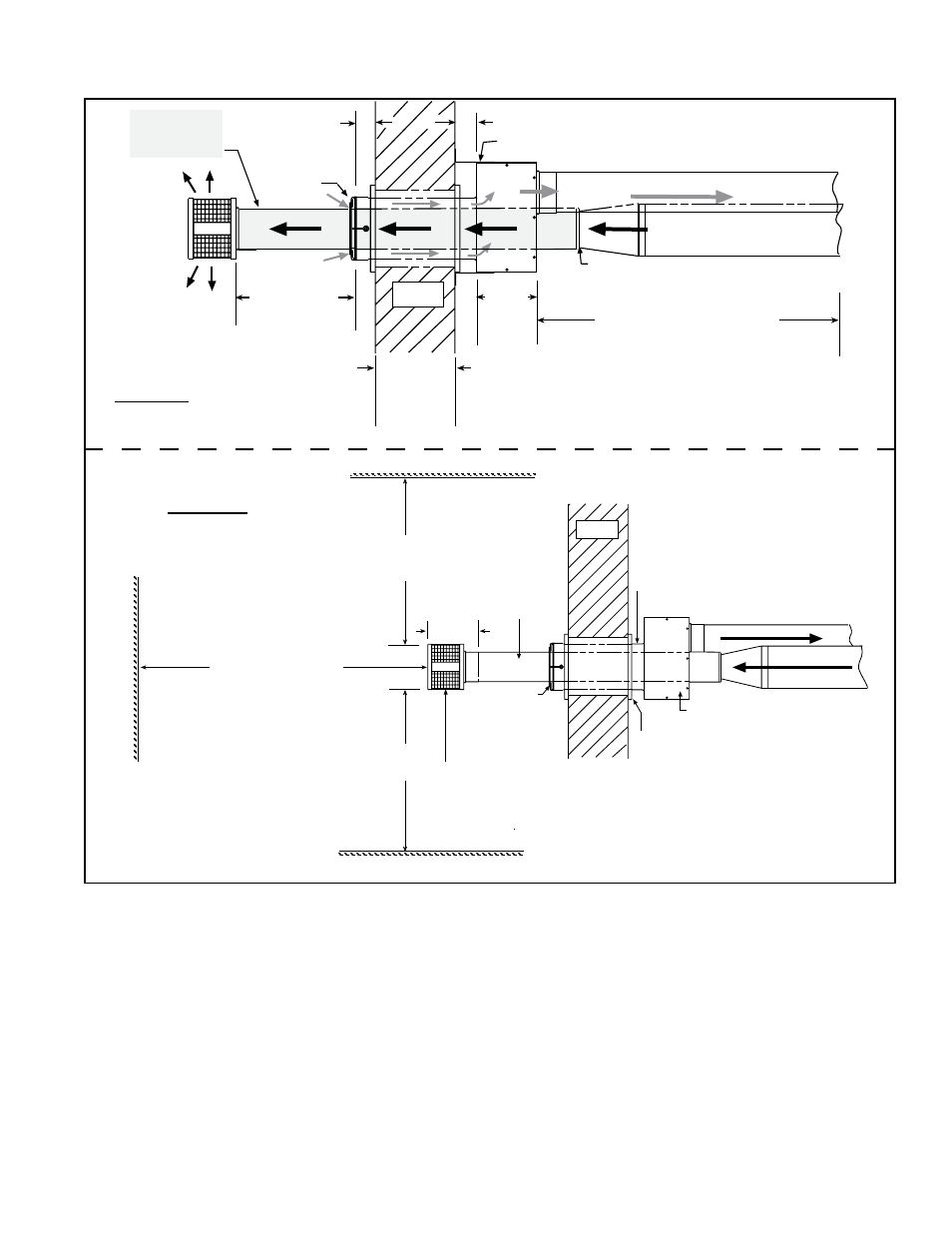
16 (406mm)
minimum
24 (610mm)
maximum
Concentric
Adapter
Box
Wall
Screened
Exhaust
Cap
Inlet Air
Guard
Combustion Air to heater (seal joints)
Vent (Flue Exhaust) Pipe
from heater (seal joints)
Furnace
Distance between the
Concentric Adapter Box
and the Furnace Section.
For Maximum Length,
see Table on page 16.
Minimum length is 5 ft (1.5M).
Attach double-vent pipe to vent run no
more than 6 (152mm) from the box. A
taper-type reducer is required.
Attach box to wall with brackets.
One piece of
Double-Wall
Vent Pipe
2 (51mm)
6
(152
mm)
1 (25mm)
minimum
48
(1219mm)
maximum
2 (51mm) if wall is combustible
Top View
6-15/16 (176mm)
Concentric Adapter Box
Double-Wall
Vent Pipe -
Pitch to
Drain
Thimble
Combustion Air Pipe - Pitch to Drain
3 ft (1M)
minimum
3 ft (1M)
minimum
6 ft (1.8M) minimum
Adjoining Building
Building Projection
Building Overhang
W a l l
Inlet Air
Guard
Exhaust (Vent) Cap
IMPORTANT: Install exhaust cap so the baffles
are positioned at 12:00, 3:00, 6:00, and 9:00 oclock.
Side View
FIGURE 17 - Installation of a Typical Separated-Combustion Unit with Horizontal Vent and
Combustion Air Pipes (Option CC6)
Use a taper-type reducer to attach the 5" double-wall
vent pipe to the 6" or 7" single-wall or Category III vent
pipe run. Follow the instructions in
FIGURE 12, page 17.
8. Attach the exhaust (vent) cap to the end of the
vent pipe. Align the cap so that its baffle strips are
positioned on the horizontal and vertical centerlines (See
FIGURE 17). Follow the instructions in FIGURE 11, page
16, to attach the exhaust cap. (
NOTE: If vent pipe is
inserted from outside, cap may be attached before the
double-wall vent pipe is installed. If cap is attached first,
be sure the baffle strips are positioned correctly when
attaching the vent terminal pipe to the vent run.)
9. Seal the vent pipe. Verify that the double-wall section
of vent pipe has a slight downward drop (1/4” per foot /
6mm per 305mm) toward the vent terminal end. Use
10. Attach the indoor combustion air pipe. If using 6"
pipes, attach the single-wall combustion air pipe run to
the collar on the concentric adapter box with sheetmetal
screws. If using 7” pipe, install a taper type enlarger as
illustrated In
FIGURE 14, page 18.
Seal joints with tape or sealant.
Installation of the horizontal vent and combustion air sys-
tem on your separated-combustion unit is complete.
Ver-
ify compliance with all venting installation require-
ments, pages 15-18, and illustrated in FIGURE 17.
silicone sealant and seal the circumference of the pipe
and the opening of the box. Seal the area around the
pipe completely.