Form i-sscbl/rpbl, page 36 – Reznor RPBL Unit Installation Manual User Manual
Page 36
Form I-SSCBL/RPBL, Page 36
FIGURE 40D - Position
the remaining side
connector over the
duct flanges. Attach
to the top and bottom
connectors with 3/4"
screws creating a "U"
shaped rectangular
frame that joins the
duct flanges on all
four sides.
Top screws
should be
vertical.
Bottom
screws
should be
horizontal.
1) Locate
Mounting Screw
2) Measure up 6" (152mm)
FIGURE 40E
3) Drill 7/8" Hole
FIGURE 34F
On the furnace
section, remove
the center hole
plug
7
8
9
10
12
13
14
15
16
17
18
19
20
21
L1
L2
8
BL
BK
W
7
BR
L1
L2
62
63
63
62
BL
BR
BR
4
5
RELAY CONTACTS
DISCHARGE DAMPER
2
DISCHARGE DAMPER MOTOR
WITH AUXILIARY SWITCH
L1
L1
L2
L2
BL
R
O
BR
CW
COM
CCW
FUSE
8.0 AMP
BK
BK
BK
W
W
11
R
6
40 VA. DISCHARGE DAMPER MOTOR
TRANSFORMER
26
25
24
22
23
27
BL
T3
L3
208/3/60
GRD
L1
G
BK
CONTACTS
BLOWER RELAY
BK
1
3
S
BK
BK
L2
T2
CONTACTS
BLOWER MOTOR
CONTACTOR
L1
OVERLOAD
RELAY
T1
96
O.L.
95
W
CR
12
A2
A1
W
BLOWER MOTOR
CONTACTOR COIL & O.L.
7 - 8 - 9
L2
MOTOR
BLOWER
24V
BR
208V
R
Y
BL
BK
*
*
*
*
WIRES SHIPPED IN DOWNTURN
PLENUM FOR FIELD WIRING
BK
CONTACTS
FAN CONTROL
8
BL
8
BL
8
8
BL
BL
BL
8
1
28
SWITCH
CONTROL
ON-OFF
DP-ST
8
Y
DISCHARGE DAMPER
AUXILIARY SWITCH
SET TO CLOSE WHEN
DAMPER IS A 20% OPEN
CONTACTS
FAN CONTROL
BL
1
R
Y
52
3
Y
52
3
R
Y
52
COM
NO
Y
NC
10
R
10
10
10
R
R
R
10
R
10
10
R
R
HEAT PERMISSIVE
RELAY CONTACTS
BK
35
2
4
BK 34
BR
22
Y
POST PURGE
RELAY CONTACTS
BL
R
2
5
53
4
PR
Y
R
R
R
3
CR
27
BR
1
7
3
25
CR
3
3
CR
CR
24
23
CR
1
1
1
7
BK
3
21
CR
1
BR
BR
EXHAUST
15 - 16
RELAY COIL
12
RELAY COIL
BLOWER
27 - 28
RELAY COIL
21
HEAT PERMISSIVE
RELAY COIL
BR
BR
BR
7
7
7
7
7
HEATER
RELAY COIL
39
POST PURGE
BR
7
H1
24V
208V
X1
H2
X2
H3
200 VA CONTROL
TRANSFORMER
BR
BK
W
*
*
DISCONNECT SWITCH
OPTIONAL FIELD WIRING
OPTIONAL FACTORY WIRING
FACTORY WIRING
FIELD WIRING
REMOTE CONSOLE
BLOWER COMPARTMENT
UNIT #2
UNIT #1
WHITE - W
PURPLE - PR
BLUE - BL
GREEN - G
YELLOW - Y
ORANGE - O
RED - R
BROWN - BR
BLACK - BK
WIRING CODE
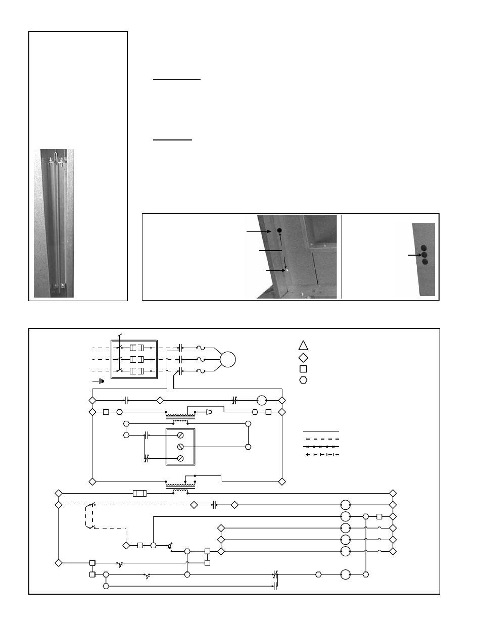
FIGURE 40G - Sample of a Partial Wiring Diagram showing Typical Field-Wiring Connections for
Optional Discharge Damper
3) Refer to
FIGURE 40E. On the leg of the downturn plenum next to the cooling
coil cabinet locate the mounting screw illustrated. Measure up 6" (152mm). At
same centerline as the screw, drill the first 7/8" hole.
Second Hole:
1) Remove the cooling coil access panel(s).
2) Locate the coil blockoff plate. Measure up 4" (102mm) from the bottom of the
blockoff plate. At that location, find the center point of the blockoff plate and drill
a 7/8" hole. The hole should be approximately even with the hole drilled in the
downturn plenum leg.
Third Hole:
On the cabinet leg on the entering air side of the cooling coil cabinet, measure up
10" (254mm) from the bottom pan. At that height, measure in 4" (102mm) from
the edge and drill a 7/8" hole.
b) On the outside of the furnace section (where the flanges were joined in Step 4),
locate the three hole plugs. Remove the center plug exposing a 7/8" hole in the
cabinet leg. See
FIGURE 40F.
Instructions for Lifting and Attaching Coil Cabinet (cont'd)