0 dimensions and clearances (cont'd), 1 dimensions (cont'd), 2 dimensions of outdoor model rpbl – Reznor RPBL Unit Installation Manual User Manual
Page 6
Form I-SSCBL/RPBL, Page 6
4.0 Dimensions
and Clearances
(cont'd)
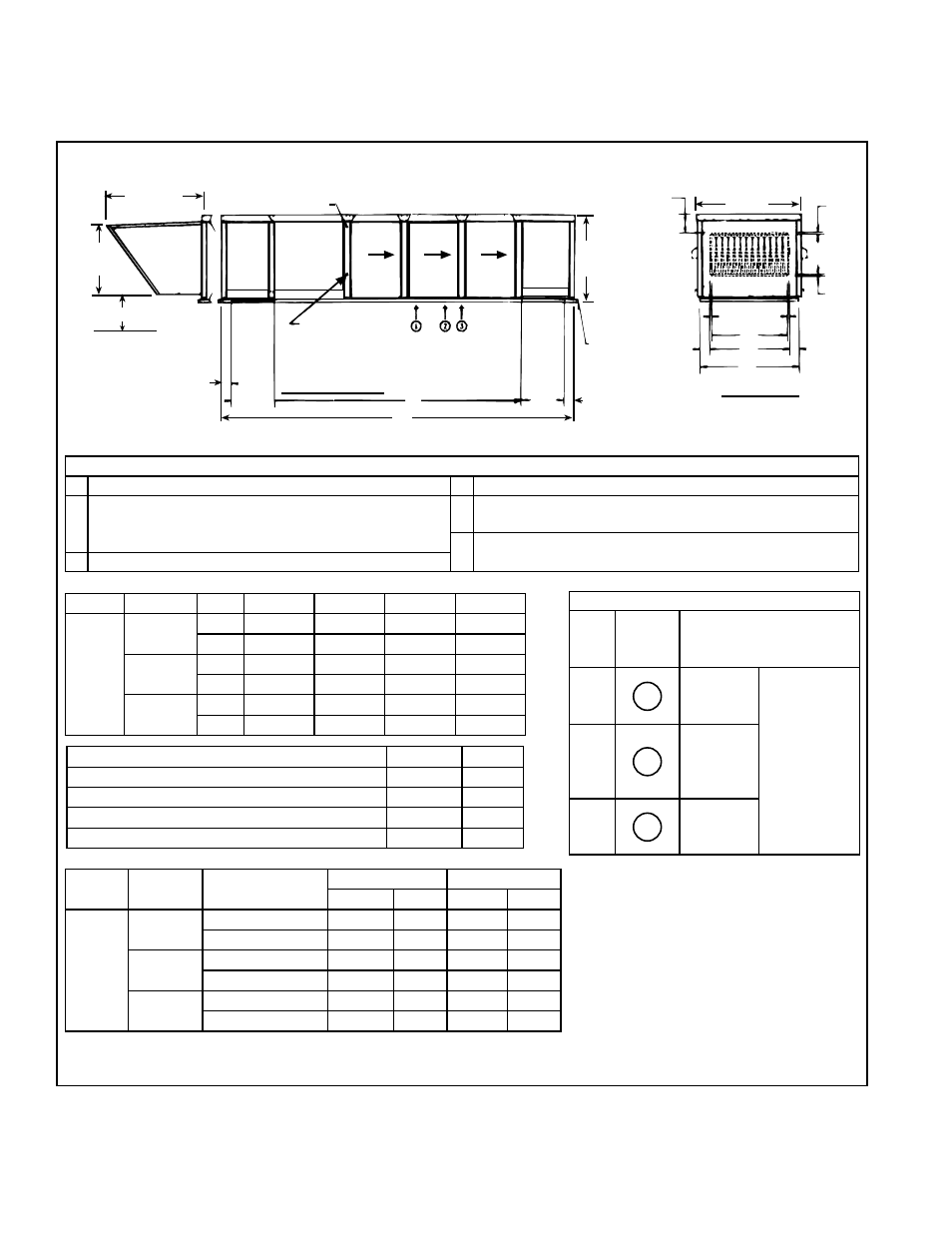
FIGURE 3 - Dimensions of Outdoor Model RPBL - inches (mm)
**Dimensions E and F listed here do not apply to system with field-attached cooling coil cabinet or cooling coil cabinet with
downturn plenum (Options AU2, AU3, AU11, AU12, AU13, and AU14). See NOTE in
FIGURE 4.
4.1 Dimensions (cont'd)
4.1.2 Dimensions of Outdoor Model RPBL
Dimension Key:
A
Width of Cabinet
D
Width of Standard Horizontal Discharge Air Opening
B
Width of Optional Downturn Plenum Discharge Air
Opening; Width of Standard Horizontal Air Inlet Opening;
and Width of Optional Return Air (Bottom ) Opening
E
Overall Length of Inside of Curb Cap
F
Distance between Optional Return Air Bottom Opening and
Optional Downturn Plenum Discharge Air Opening
C
Width of the Curb Cap
Model
Size
A
B
C
E
RPBL
500, 600
inches 47-1/8
36-5/8
45-1/8
34-1/2
mm
1216
930
1146
876
700, 1050
inches 53-3/8
42-1/8
50-5/8
40
mm
1356
1070
1286
1016
400, 800,
1200
inches 58-7/8
47-5/8
56-1/8
45-1/2
mm
1495
1210
1426
1156
Model
Size
with Downturn
Opt AQ5 or AQ8*
E**
F**
inches
mm
inches
mm
RPBL
400
No
83-3/4
2127
--
Yes
107-3/4
2737 60-5/16 1532
500, 600,
700, 800
No
109-3/4
2788
--
Yes
133-3/4
3397 86-5/16 2192
1050,
1200
No
135-3/4
3448
--
Yes
159-3/4
4058 112-5/16 2853
Approximate Gas Connection Location*
Size Drawing
Location
Approximate Distance from
inside Curb Cap on Blower
End of System
400
1
7 ft + 5 to 6
inches (2.3
meters)
The gas line
is manifolded
requiring only
one supply
connection.
The gas
connection is
at curb cap
"height" on the
control side of
the system.
500,
600,
700,
800
2
8 ft + 7 to 8
inches (2.7
meters)
1050,
1200
3
9 ft + 2 to 3
inches (2.8
meters)
*The gas line is manifolded requiring only
one supply connection; see more detail in
Paragraph 6.1. The gas connection is at
curb cap "height" on the control side of the
system.
Air Openings:
inches
mm
Standard Horizontal Air Inlet
19-1/2 x B 495 x B
Optional Return Air Opening (bottom)
19-1/2 x B 495 x B
Standard Horizontal Discharge Air Opening
18 x E
457 x D
Opt Discharge Air Opening (w/Downturn Plenum) 19-1/2 x B 495 x D
43-17/32
(1106)
Field Wiring
Control Voltage
A
8-15/32
(215)
3/4
(19)
3/4
(19)
18(457)
3/4
(19)
3/4
(19)
D
Front View
(standard horizontal
discharge)
4-1/4
(108)
4-1/4
(108)
B
C
40-1/8
(1019)
Optional Downturn Plenum
Furnace
Airflow
Furnace
Airflow
Furnace
Airflow
Optional
100%
Outside
Air Hood
31-11/32
(796)
Optional
Return
Air
Opening
Field Wiring
Line
Voltage
Gas Connection Location
(only one connection;
see table below)
Optional
Supply
Air
Opening
CurbCap
with
Suspension
Holes
4-3/32
(104)
Left Side View
19-1/2
(495)
F
E
19-1/2
(495)
4-3/32
(104)
14 (356mm) Minimum
Clearance
Blower
Cabinet