0 suspension and mounting (cont'd), 4 mounting outdoor model rpbl (cont'd) – Reznor RPBL Unit Installation Manual User Manual
Page 10
Form I-SSCBL/RPBL, Page 10
5.0 Suspension
and Mounting
(cont'd)
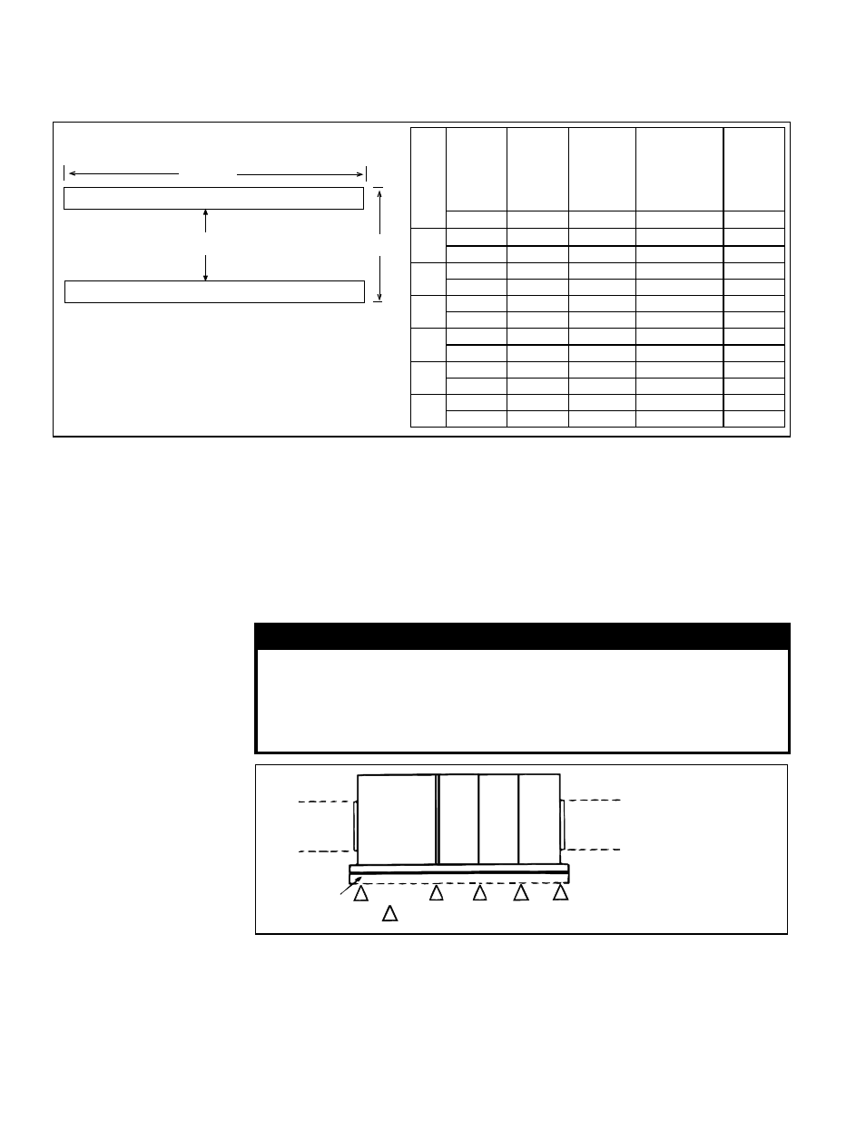
FIGURE 7 - Mounting Support Dimensions
A
B
4x4 Treated Lumber
Leave both
ends open
for ventilation.
Size
Standard
Heater(s)
and
Blower
Package
With
Option
AQ5 or
AQ8
Downturn
Plenum
With
Option AU2
or AU3
Cooling
Coil
Cabinet
With Option
AU 11, 12, 13,
or 14 Cooling
Coil Cabinet
with Downturn
Plenum
All
"A"
"A"
"A"
"A"
"B"
400
82-1/4"
106-1/4"
150-1/4"
174-1/4"
54-1/2"
2089mm
2699mm
3816mm
4426mm
1384mm
500/
600
108-1/4"
132-1/4"
165-1/4"
189-1/4"
43-9/16"
2750mm
3359mm
4197mm
4807mm
1106mm
700
108-1/4"
132-1/4"
170-3/4"
194-3/4"
49-1/16"
2750mm
3359mm
4337mm
4947mm
1246mm
800
108-1/4"
132-1/4"
176-1/4"
200-1/4"
54-1/2"
2750mm
3359mm
4477mm
5086mm
1384mm
1050
134-1/4"
158-1/4"
196-3/4"
220-3/4"
49-1/16"
3410mm
4020mm
4997mm
5607mm
1246mm
1200
134-1/4"
158-1/4"
202-1/4"
226-1/4"
54-1/2"
3410mm
4020mm
5137mm
5747mm
1384mm
If the rails are being laid directly on the roof, position them as shown in
FIGURE 7. Set
the system on the rails, leaving the "ends" underneath open for ventilation.
If the treated wooden rails are not being placed directly on the roof surface, cross-
supports should be placed underneath the rails at the ends of the unit and at all cabinet
"joints" (between the blower cabinet and the heater section and between the furnace
and the optional downturn plenum cabinet). See
FIGURE 8.
The field-supplied, weather-resistant cross-support structure must be adequate for the
weight of the system, and all cross-supports should run the entire width of the system
supporting the 4x4 wooden rails at the recommended locations. Do not enclose the
area under the furnace; leave space for ventilation.
WARNING
S
Do not close or block the openings under each end of a system
mounted on 4x4 treated wooden rails; the space under the furnace
MUST be left open for ventilation.
If cross supports are used under the 4x4 rails, do not enclose the
area under the furnace; leave open space for ventilation.
FIGURE 8 - Cross-
Support Locations
for Outdoor Systems
when the wooden 4x4
rails supporting the
length of the system are
supported by additional
structure
• A structure
height of at least
12" (305mm) is
recommended in
snow areas.
• Do not enclose the
area underneath
the furnace;
leave space for
ventilation.
Field-
Supplied
Duct
Blower
Cabinet
Duct
Furnace
Field-
Supplied
Duct
4x4 Treated
Lumber
= Support Locations
Duct
Furnace
Duct
Furnace
5.4 Mounting Outdoor Model RPBL (cont'd)
5.4.4 Mounting on a
Roof Curb - Applies
to Outdoor Model
RPBL
Whether using an optional roof curb supplied with the system or a field-supplied curb,
the curb must be secure, square and level. The top surface of the roof curb must be
caulked with 1/4" x 1-1/4" sealant tape or two 1/4" beads of suitable sealant. The unit
must be sealed to the curb to prevent water leakage into the curb area due to wind
blown rain and capillary action. Except for the curb assembly details, the information
and requirements in this section apply to all curbs. See
FIGURES 9A, 9B, and 9C and
the curb installation instructions.
5.4.3 Mounting Outdoor Models on Field-Supplied Supports
(without a roof curb) - Applies to Model RPBL (cont'd)