Reznor RPBL Unit Installation Manual User Manual
Page 33
Form I-SSCBL/RPBL, P/N 149159 R7, Page 33
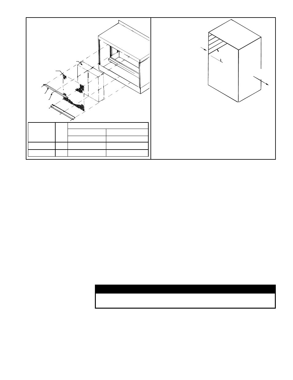
45°
Airflow
to S
pace
Out
side
Airflow
FIGURE 37 -
Media must be
installed with 45°
angle sloping
downward toward
the incoming
outside air.
IMPORTANT: The media is made up of two
different sheets of cooling material. Each sheet
has its own unique angle. When replacing the
cooling media, BE CERTAIN that the 45° angle
slopes downward toward the incoming outside
air (as illustrated above). If the media is not
installed properly, water blowoff from the media
pads will occur.
Pad
Screen
Pad
Retainer
Screw
Media
Pad Sizes
(inches)
Qty
Replacement Part No. (each)
Rigid Cellulose Rigid Glass Fiber
12"
12"
48 x 12
4
107194
107201
48 x 8-5/8
1
107195
107202
FIGURE 36 - Removal
and Replacement of
Evaporative Cooling
Module Media
8. Replace the two side screen retainers by fitting them between the side of the
media pad and the side of the cooling module. The retainers should fit snugly,
pinching the screen against the media pads.
9. Replace the bottom pad retainer by securing the retainer between the pad and the
reservoir pan. Fasten with the three sheetmetal screws removed in Step 2.
10. Replace the top pad retainer by securing the retainer between the pad and top of
the cooling module. Fasten with the three sheetmetal screws removed in Step 1.
Water Feed Line and Distribution Piping – Annually, the water supply line and the
water distribution line (either PVC pipe or water sock) should be flushed of debris and
contaminants.
1. Remove the media pads following the instructions above.
2. Remove the water feed line from the downstream side of the ball valve and
unscrew the water bleed line barbed hose fitting.
3. Force a fresh water supply up through the water inlet hose and thoroughly flush
the distribution line.
4. Re-assemble, being careful to install media with air flow direction as shown in
FIGURE 37.
Water Pump and Inlet Basket Screen (Does not apply to module with optional timed
metering system.)
– Annually, the pump and inlet basket should be removed, disas-
sembled and cleaned.
WARNING
Do not expose pump motor or any part of the electrical box to
water. Evaporative cooling pump is NOT submersible.
1. Disconnect the power supply to the unit.
2. Remove the junction box door and disconnect the two power supply wires from
the terminal block inside the junction box.
3. Disconnect the water feed line hose from the upstream side of the ball valve.
4. Unscrew the four sheetmetal screws holding the junction box to the cooling
module. Remove the junction box-pump-float switch assembly.
5. Dislodge the inlet basket screen from the pump and clean any buildup of debris
and dirt. Carefully remove the base cover plate from the bottom of the pump.