0 dimensions and clearances, 1 dimensions, 1 dimensions of indoor model sscbl – Reznor RPBL Unit Installation Manual User Manual
Page 5: Top view of curb cap assembly
Form I-SSCBL/RPBL, P/N 149159 R7, Page 5
Vent/Combustion Air
Terminal Kit - Required
on ALL SSCBL
Installations
All Model SSCBL installations require a vent/combustion air kit (Option CC2 or CC6)
including a concentric adapter box for each duct furnace. See page 19 (Option CC6)
or page 22 (Option CC2) for the component list of each kit. Be sure all of the factory-
supplied and field-supplied parts needed for the vent/combustion air kit(s) are at the
job site.
Other shipped-separate options could include a roof curb, an outside air hood, a gas
shutoff valve, a thermostat, an optional control switch, a remote console, a vent exten-
sion, a gas supply regulator, and/or a disconnect switch. If ordered with either an
evaporative cooling module or a DX or chilled water cooling coil module, the module
is shipped separately. A drain and fill or freeze kit and a water hammer arrestor are
shipped-separate options for an evaporative cooling module.
4.0 Dimensions and Clearances
4.1 Dimensions
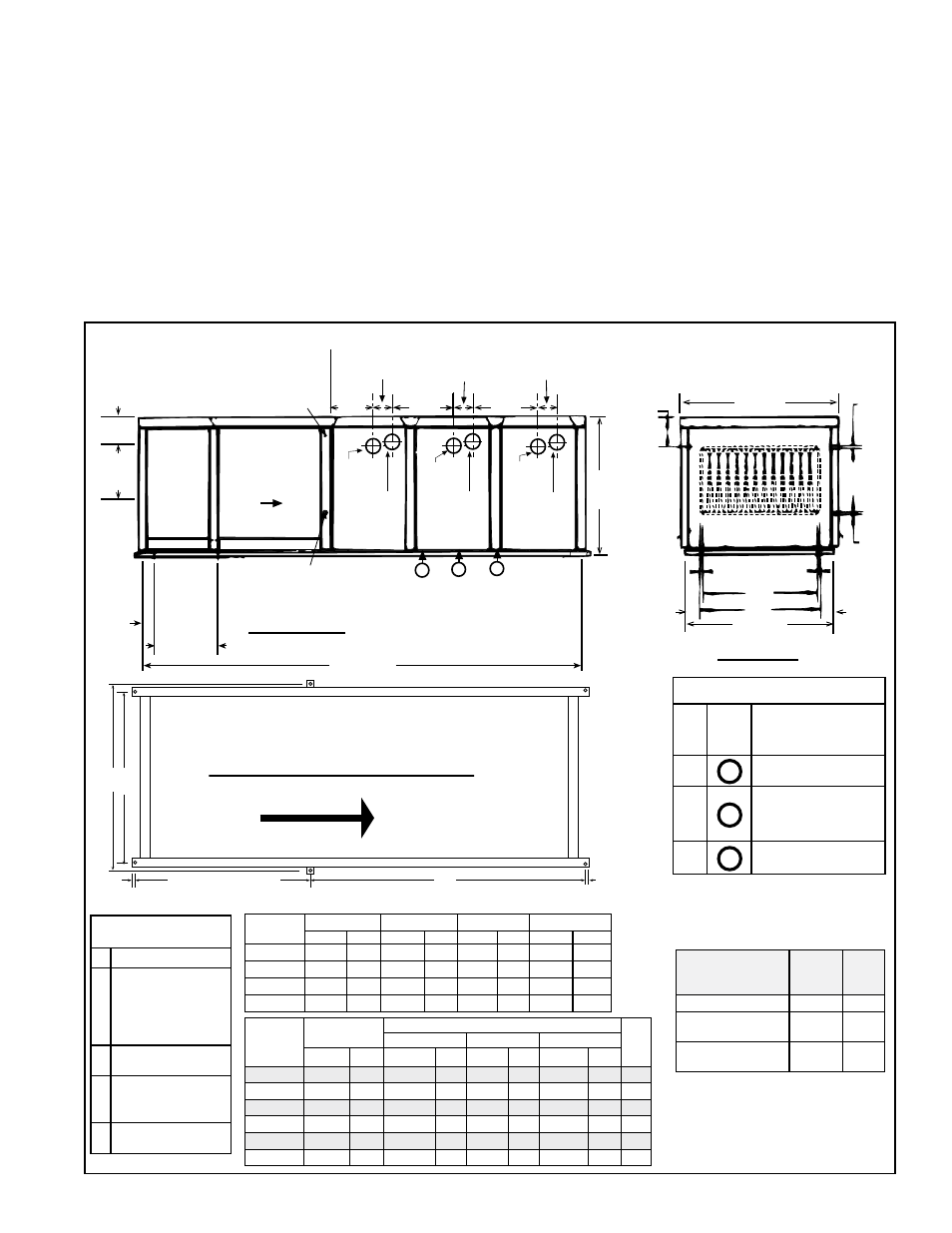
FIGURE 2 - Dimensions of Indoor Model SSCBL - inches (mm)
Key for FIGURE 2
(Codes A-E):
A
Width of Cabinet
B
Width of Horizontal
Air Inlet Opening;
Width of Optional
Return Air (Bottom)
Opening
C
Width of the Curb
Cap
D
Width of Horizontal
Discharge Air
Opening
E
Overall Length of
Inside of Curb Cap
SSCBL
Size
A
B
C
D
inches mm
inches mm inches mm inches
mm
400
58-7/8 1495 47-5/8 1210 56-1/8 1426 45-1/2 1156
500, 600 47-7/8 1216 36-5/8 930 45-1/8 1146 34-1/2 876
700, 1050 53-3/8 1356 42-1/8 1070 50-5/8 1286
40
1016
800, 1200 58-7/8 1495 47-5/8 1210 56-1/8 1426 45-1/2 1156
5 (127)
19-1/2
(495)
4-3/32
(104)
Field Wiring
Control Voltage
11-1
1/32
(288)
7-13/32
(188)
7-13/32
(188)
7-13/32
(188)
18-1/2 (470)
18-1/2 (470)
Blower
Cabinet
Furnace
Field Wiring
Line Voltage
Left Side View
E
19-1/2
(495)
Optional
Return
Air
Opening
8-15/32
(215)
1
2
3
Gas Connection Location
(only one connection per unit;
see table below on right.)
Vent Pipe
Collar,
6 O.D.
Inlet Air
Collar,
6 I.D.
Furnace
Furnace
Airflow
Vent Pipe
Collar,
6 O.D.
Vent Pipe
Collar,
6 O.D.
Inlet Air
Collar,
6 I.D.
Inlet Air
Collar,
6 I.D.
40-1/8
(1019)
A
3/4
(19)
3/4
(19)
3/4
(19)
3/4
(19)
4-1/4
(108)
4-1/4
(108)
Front View
D
B
C
18
(45)
SSCBL
Size
E**
Suspension Dimensions
No. of Hangers
F
G
H**
inches
mm
inches
mm
inches mm
inches
mm
400
83-1/2 2121 59-9/16 1513 54-3/8 1381 27-3/32 688
6
500, 600 109-1/2 2781 48-9/16 1233 43-3/8 1102 53-3/32 1352 6
700
109-1/2 2781 54-1/16 1373 48-7/8 1229 53-7/32 1352 6
800
109-1/2 2781 59-9/16 1513 54-3/8 1381 53-7/32 1352 6
1050
135-1/2 3442 54-1/16 1373 48-7/8 1229 79-7/32 2012 6
1200
135-1/2 3442 59-9/16 1513 54-3/8 1381 79-7/32 2012 6
Approximate Gas
Connection Location *
Size
Drawing Location (above)
Approx Distance from
inside Curb Cap on
Blower End of System
400
1
7 ft + 5 to 6 inches
(2.3 meters)
500,
600,
700,
800
2
8 ft + 7 to 8 inches
(2.7 meters)
1050,
1200
3
9 ft + 2 to 3 inches
(2.8 meters)
Top View of Curb Cap Assembly
Suspension Point Dimensions
G
F
H
Airflow
58-25/32 (1493)
3/4
(19)
3/4
(19)
Air Opening
Descriptions &
Dimensions
inches
mm
Horizontal Air Inlet
19-1/2xB 495xB
Optional Return Air
Opening (bottom)
19-1/2xB 495xB
Horizontal Discharge
Air Opening
18xD
457xD
*The gas line is manifolded requiring
only one supply connection. The gas
connection is at curb cap "height" on
the control side of the system.
4.1.1 Dimensions of Indoor Model SSCBL
**Dimensions E and H listed here do not
apply to a system with a field-attached
cooling coil cabinet (Option AU2 or AU3);
see NOTE in
FIGURE 4.