Reznor RPBL Unit Installation Manual User Manual
Page 47
Form I-SSCBL/RPBL, P/N 149159 R7, Page 47
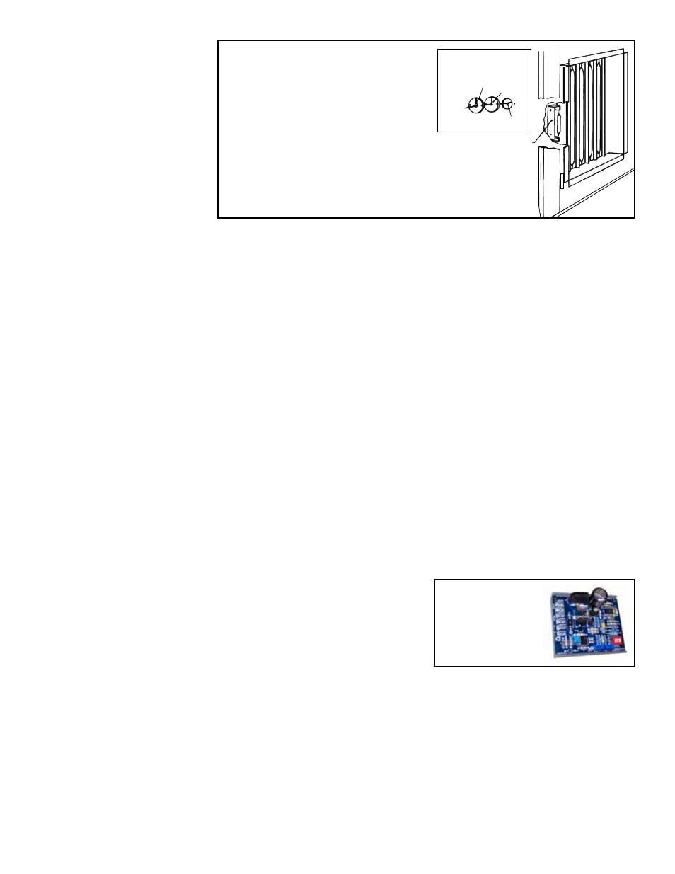
Sensor Bracket
(NOTE: Bracket
may not be the
same as the one
illustrated.)
Sheetmetal
Retaining
Plate
Gasket
Sensor Capillary
1. Remove access panel in the ductwork
adjacent to the control compartment
access panel.
2. Element is retained by either spring
clips or cable straps.
3. Round gasket and metal retaining
plate provide airtight seal for capillary
and must be removed to remove the
element.
FIGURE 49 - Duct Temperature
Sensor Location
8.8.4 Optional
Electronic Modulation
The type and capability of the electronic modulation system depends on the option
selected. Electronic modulation options are identified by a suffix to the Serial No.
printed on the heater rating plate. AG7 is identified as MV-1; AG8 is identified as MV-3;
AG9 is identified as MV-4; AG21 is identified as MV-A; AG39 is identified as MP-1; and
AG40 is identified as MP-2. AG39 and AG40 are available only on Size 400. AG41 is
identified as MP3 and AG42 is identified as MP4. Both AG41 and AG42 apply only to
Sizes 500, 600, 800, and 1200.
Installation Note: Sizes
400, 700, 800, 1050,
and 1200 with electronic
modulation gas controls
require a minimum of 6"
w.c. natural gas supply
pressure.
Electronic Modulation between 50% & 100% Firing Rate
(Options AG7,
AG8, AG9)
Depending on the heat requirements as established by the thermistor sensor, the
burner modulates between 100% and 50% firing. The thermistor is a resistor that is
temperature sensitive in that as the surrounding temperature changes, the Ohms resis-
tance changes through the thermistor. This change is monitored by the solid state
control center (amplifier) which furnishes varying DC current to the modulating valve to
adjust the gas input.
Each modulating valve is basically a regulator with electrical means of raising and
lowering the discharge pressure. When no DC current is fed to this device, it functions
as a gas pressure regulator, supplying 3.5" w.c. pressure to the main operating valve.
Refer to the wiring diagram supplied with the furnace for proper wiring connections.
Electronic modulation for heating controlled by a specially designed room thermo-
stat (60°-85°F) is identified as Option AG7. Electronic modulation control systems for
makeup air applications controlled by a duct sensor and temperature selector (55-
90°F) are identified as either Option AG8 or Option AG9. The temperature selector set-
ting for Option AG8 is on the amplifier; Option AG9 has a remote temperature selector.
Both systems are available with an override thermostat.
Computer Controlled
Electronic Modulation
between 50% and 100%
Firing Rate (Option
AG21)
FIGURE 50 -
Maxitrol
conditioner in
Options AG21,
AG40, and AG42
With this option the furnace is equipped
with a Maxitrol signal conditioner which
operates much the same way as the ampli-
fier above to control the regulator valve.
The conditioner accepts an input signal of
either 4-20 milliamps or 0-10 volts from a
customer-supplied control device such as
a computer. With the dip switches on the
conditioner in the "on" positions, the conditioner accepts a 4-20 milliamp signal. In the
"off" positions, the conditioner accepts a 0-10V signal. The conditioner converts the
signal to the 0 to 20 volt DC current required to control the modulating valve. Tempera-
ture selection is through the computer software.
Electronic Modulation
between 25% and 100%
Firing Rate), Options
AG39, AG40, AG41,
AG42 -
Available only
with natural gas
A Size 400 unit equipped with electronic modulation Option AG39 has a 25%-100%
firing range (4:1 turndown ratio). Option AG41 applies to Sizes 500, 600, and 800 with
two furnaces and Size 1200 with three furnaces. The furnace closest to the blower is
equipped with the electronic modulation option. The other furnace(s) have two-stage
burner control from outside air temperature sensors identified as heat stage control-
lers. Option AG41 provides 6:1 turndown with two furnaces and 8:1 turndown with
three furnaces.