0 mechanical, 1 gas piping and pressures – Reznor RPBL Unit Installation Manual User Manual
Page 13
Form I-SSCBL/RPBL, P/N 149159 R7, Page 13
6.0 Mechanical
6.1 Gas Piping and
Pressures
WARNING
This appliance is equipped for a maximum gas supply pressure of 1/2
psi, 3.5 kPa, or 14 inches water column. NOTE: Supply pressures higher
than 1/2 psi require installation of an additional service regulator exter-
nal to the unit.
Pressure Testing Supply Piping
Test Pressure Above 1/2 PSI: Disconnect the heater and manual valve from the gas
supply which is to be pressure tested. Cap or plug the supply line.
Test Pressure Below 1/2 PSI: Before testing, close the manual valve on the heater.
WARNING
Manifold gas pressure must never exceed 3.5" w.c. for natural gas or
10" w.c. for propane gas.
All piping must be in accordance with requirements outlined in the National Fuel Gas
Code ANSI/Z223.1 (latest edition) or CSA B149.1 and B149.2. (See Paragraph 1.4.)
Gas supply piping installation should conform with good practice and with local codes.
These separated-combustion units for natural gas are orificed for gas having a heating
value of 1000 (±50) BTU per cubic ft. If the gas at the installation does not meet this
specification, consult the factory for proper orificing.
Pipe joint compounds (pipe dope) shall be resistant to the action of liquefied petroleum
gas or any other chemical constituents of the gas being supplied.
Install a ground joint union and manual shutoff valve upstream of the unit control sys-
tem. The 1/8" plugged tapping in the shutoff valve provides connection for supply line
pressure test gauge. The National Fuel Gas Code requires the installation of a trap with
a minimum 3" drip leg. Local codes may require a longer drip leg, typically 6".
After all connections are made, disconnect the pilot supply at the control valve and
bleed the system of all air. Reconnect the pilot line and leak test all connections by
brushing on a soap or leak-detecting solution.
WARNING
All components of a gas supply system must be leak tested prior
to placing the equipment in service. NEVER TEST FOR LEAKS
WITH AN OPEN FLAME. See Hazard Levels, page 2.
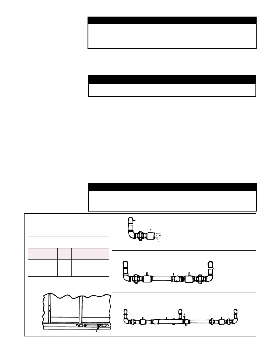
Gas Connection Size
(Not Gas Supply Line Size)
SSCBL /
RPBL
400
500, 600, 700,
800, 1050, 1200
Natural Gas
1"
1-1/4"
Propane
1"
1-1/4"
Gas Connection
Gas Inlet
Curb
Cap
FIGURE 10 - Gas Connection and
Gas Train Manifold Arrangements
SSCBL or RPBL with 2 furnace sections
To furnace
Manual
shutoff
Adapter wth 1/8 NPT plugged
hole for pressure gauge connection
Gas Inlet
To furnace 1
Gas Inlet
Adapter wth
1/8 NPT plugged
hole for pressure
gauge connection
Manual
shutoff
To furnace 2
Manual
shutoff
To Furnace 1
Manual
Shutoff
Valve
Gas Inlet
To Furnace 2
Adapter with 1/8 NPT
plugged hole for pressure
gauge connection
To Furnace 3
Manual
Shutoff
Valve
SSCBL or RPBL with 3 furnace sections
SSCBL or RPBL with
1 furnace section