0 mechanical (cont'd), 2 venting and combustion air (cont'd), Cont'd) – Reznor RPBL Unit Installation Manual User Manual
Page 20
Form I-SSCBL/RPBL, Page 20
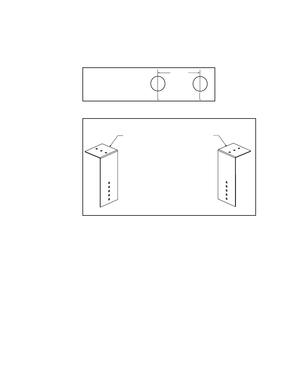
FIGURE 16B - Brackets
for Attaching the
Concentric Adapter Box
to the Wall
1) Attach the Brackets to the Box - The 6
(152mm) portion of each bracket is
designed with five 7/32 diameter holes
so that attachment to the box can be
adjusted.
If the wall is combustible, position brackets to
allow for a 2 (51mm) clearance between the
box and the wall.
Adjust bracket attachment to allow for the slight
downward pitch of the terminal vent pipe.
After careful positioning, use sheetmetal screws
to attach the brackets. NOTE: If any holes are
made in the box in error, they must be sealed.
2) Attach the Box to the Wall (Step 5)
When the box is attached to the wall in Step 5,
use the 2-1/2 (64mm) portion of the brackets.
To adjust to construction each bracket has
three 7/32 diameter holes.
C
C
26-1/8
(664mm)
minimum
With more than one
furnace section, prepare
one hole per furnace
with spacing as shown.
FIGURE 16A - Prepare
holes so that there
is a minimum of 26-
1/8" (664mm) between
centerlines of each
terminal pipe.
b) Attach the outside portion of the combustion air pipe to the box. Determine
the length by measuring the bracket length from box to wall, plus the wall thickness,
plus 2" (51 mm). (The inlet air pipe should extend beyond the outside wall
approximately 2" (51mm).)
Attach the inlet air pipe to the collar of the concentric adapter with sheetmetal screws
and seal.
5. Attach the concentric adapter box to the wall. Insert the combustion air pipe
through the wall.
Attach the brackets (FIGURE 16B) to the wall. On the outside, caulk
or flash the inlet air pipe. Flashing is field-supplied.
6. Position the inlet guard over the end of the combustion air pipe. See FIGURE
17. Attach the guard to the inlet air pipe with the four 1/2" long screws.
7. Determine length and install the double-wall terminal vent pipe.
a) Determine length of pipe. The length of the vent pipe is determined by the
installation within the maximum and minimum requirements. See
FIGURE 17, to
determine lengths of each segment and calculate the total length required. The vent
pipe extending through the box and the inlet air pipe
must be one piece of double-
wall vent pipe without joints. The transition to the single-wall or Category III vent
pipe run, must be a maximum of 6” (152mm) from the heater side of the box.
b) Install double-wall terminal vent pipe. Being sure the vent pipe is in the proper
flow direction, slide the end through the box. Position the vent pipe so that it will
extend between 16" (406mm) and 24” (610mm) past the end of the combustion air
pipe and no more than 6” (152mm) out of the box toward the heater.
6.2 Venting and
Combustion Air
(cont'd)
6.0 Mechanical
(cont'd)
6.2.1.2 Horizontal Vent Instructions - Model SSCBL
(cont'd)
4. Prepare the Concentric Adapter Box
a) Attach the brackets to the box. Follow the instructions in FIGURE 16B.
3. Prepare a hole through the outside wall for the 8" (203mm) diameter
combustion air pipe. Outside wall construction thickness should be between 1"
(25mm) minimum and 48" (1143mm) maximum. The larger diameter combustion air
pipe serves as clearance for the vent pipe on non-combustible construction. A thimble
may be required depending on wall construction and/or local codes.
When installing a system with more than one furnace section, a minimum or 26-1/8"
(664mm) is required between the centerlines of each terminal pipe (
FIGURE 16A).