3 thermostat and control wiring, 0 electrical supply and controls (cont'd), 2 supply voltage and wiring (cont'd) – Reznor RPBL Unit Installation Manual User Manual
Page 42
Form I-SSCBL/RPBL, Page 42
Disconnect Switch
A disconnect switch is a required part of this installation. The disconnect switch may be
fusible or non-fusible. When providing or replacing fuses in a fusible disconnect switch,
use dual element time delay fuses and size according to 1.25 times the maximum total
input amps. A disconnect switch is available as optional equipment or may be supplied
locally. When installing the disconnect switch, be careful that the conduit and switch
housing are clear of all service panels. Allow at least four feet (1.2M) of service room
between the disconnect switch and any removable service panels.
7.3 Thermostat and
Control Wiring
Approximate Ampere Rating of 24-Volt Controls
Fan Control Time Delay ........ .12 amps
Spark Ignition System ........... .1 amps
Maxitrol Gas Control System .51 amps
Heater ................................... .14 amps
RBM Relay Coil .................... 2 amps
Single-Stage Gas Valve ........ .6 amps
Contactor Coil ....................... .45 amps
Two-Stage Gas Valve ........... .6 amps
Separately activated relays must be substituted at the unit thermostat connections to
cycle more than one furnace from one thermostat.
There are a variety of optional controls available as part of the gas and air control
options. Check the wiring diagram and literature supplied with the unit for operation
of factory-installed optional controls. See
FIGURE 46 for location of electrical connec-
tions (Codes 18 and 39) and standard and optional controls.
Optional shipped-separate heating and makeup air controls could include a single or
two-stage thermostat, system switches, selectrastat, freezestat, an automatic night
setback device, a Maxitrol temperature selector, potentiometer, a pressure null switch,
or a combination of these controls. Each of these should be installed according to the
manufacturer's instructions packaged with the heater.
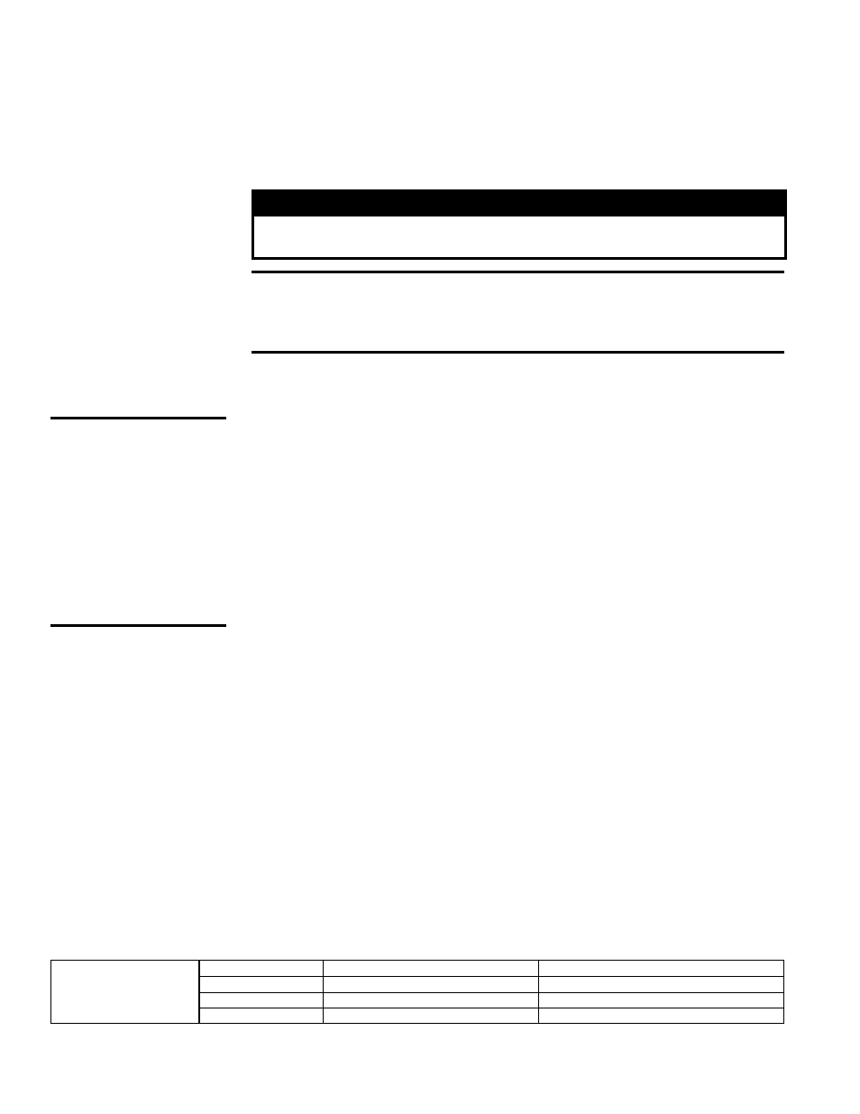
Field Control
Wiring - Length and
Gauge
Total Wire Length
Distance from Unit to Control
Minimum Recommended Wire Gauge
150'
75'
#18 gauge
250'
125'
#16 gauge
350'
175'
#14 gauge
7.0 Electrical
Supply and
Controls
(cont'd)
CAUTION: Make
sure the thermostat
has an adequate VA
rating for the total
requirements. Add
coil rating of all
relays and match
thermostat rating.
See Hazard Levels,
page 2.
Remote Console
7.2 Supply Voltage
and Wiring
(cont'd)
WARNING
If you turn off the power supply, turn off the gas. See Hazard
Levels, page 2.
CAUTION: If any of the original wire as supplied with the appliance
must be replaced, it must be replaced with wiring material having a
temperature rating of at least 105°C, except for sensor lead wires which
must be 150°C. See Hazard Levels, page 2.
The heater is equipped with a low voltage (24V) control circuit. See the wiring diagram
in the heater electrical box.
A thermostat is not supplied with the furnace. Use either an optional or a field-provided
low-voltage (24V) thermostat. Install the thermostat according to the manufacturer's
instructions.
If the low-voltage thermostat is equipped with a heat anticipator, set the anticipator at
full load control amps. See chart below for amp ratings of optional controls.
A selection of consoles is available with specific combinations of controls factory
mounted. Consoles include indicator lights for the blower and burner, an off/on system
switch, terminal block wiring, and may include optional controls. Consoles are shipped
separately for remote installation and can be either mounted on a wall or recessed.