0 mechanical (cont'd), 2 venting and combustion air (cont'd) – Reznor RPBL Unit Installation Manual User Manual
Page 24
Form I-SSCBL/RPBL, Page 24
Determine the minimum length by adding the requirements. Starting at the bottom,
the maximum the vent pipe can extend below the box is 6” (152mm);
plus 6”
(152mm) through the box;
plus length of bracket extending above the box; plus
the width of the roof;
plus the height of the outside combustion air pipe above the
roof;
plus a minimum of 3” (76mm) beyond the top of the inlet air pipe. Total is the
minimum length of the vent pipe section. If the actual piece of vent pipe is longer,
extend it further above the combustion air pipe. Do not extend it more than 6”
(152mm) below the box.
b) Install the pipe. Being sure the pipe is in the proper flow direction, slide the end
into the box and out through the combustion air pipe. Position the vent pipe so that
the end is no more than 6” (152mm) below the box. The upper end should extend at
least 3” (76mm) above the combustion air pipe.
NOTE: The double-wall vent pipe
does not attach to the box. The installer must provide support.
Follow the instructions in
FIGURE 12, page 17 for connecting the double-wall pipe to
the single-wall pipe or Category III vent pipe run. A taper-type reducer is required.
Seal the circumference of the pipe and the opening of the box with silicone sealant.
Seal the area around the pipe completely.
7. On the outside, slide the combustion air inlet over the vent pipe and fasten the
collar to the combustion air pipe with sheetmetal screws. See
FIGURE 23. Seal the
opening at the top between the vent pipe and the combustion air inlet with silicone
sealant to prevent water leakage.
8. Attach the exhaust (vent) cap. See FIGURE 23 and follow the illustrated
instructions in
FIGURE 11, page 16.
6.2 Venting and
Combustion Air
(cont'd)
6.2.1 Separated-
Combustion Model
SSCBL (cont'd)
6.0 Mechanical
(cont'd)
6.2.1.3 Vertical Vent
Instructions - Model
SSCBL (cont'd)
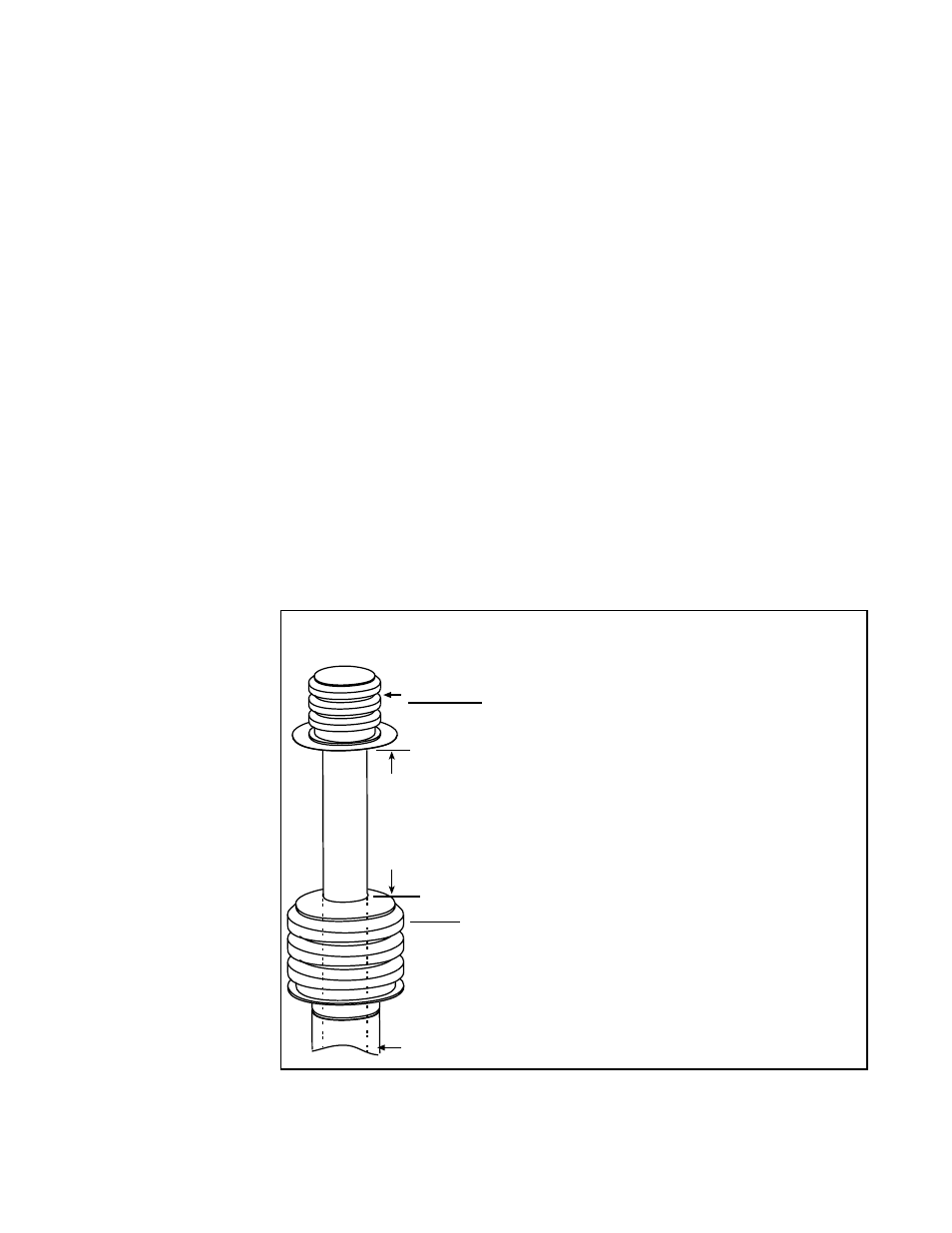
SECOND, Install the Exhaust (Vent) Terminal.
Follow the instructions in FIGURE 11, page 16.
FIRST, Install Combustion Air Inlet.
1) Slide the combustion air inlet over the vent pipe.
2) Fasten bottom of inlet to the combustion air pipe with
sheetmetal screws. Be sure not to penetrate the vent pipe.
3) At the top, completely seal the space between the vent
pipe and the air inlet with silicone.
5 Inside Diameter Double-wall V
ent Pipe
8 Diameter Single-wall Combustion Air Pipe
12 (305mm) minimum
Cold Climate NOTE: In geographic areas where
the design ambient is -10°F or lower, this minimum
height is 24 (610mm)
FIGURE 23 - Install Combustion Air Inlet and Vent Terminal
9. Attach the indoor combustion air pipe. Use sheetmetal screws to attach the
single-wall combustion air pipe run to the collar on the concentric adapter box. Seal
with tape or sealant. If using 7” pipe, install a taper type enlarger as illustrated in
FIGURE 14, page 18.
Installation of the vertical vent and combustion air system on your separated-combus-
tion unit is complete.
Verify compliance with all venting installation requirements,
pages 15-18, and FIGURE 24