0 suspension and mounting (cont'd), 4 mounting outdoor model (cont'd), 4 mounting on a roof curb - model rpbl (cont'd) – Reznor RPBL Unit Installation Manual User Manual
Page 12: Roof curb assembly and installation instructions, Figure 9c - detail of installed curb
Form I-SSCBL/RPBL, Page 12
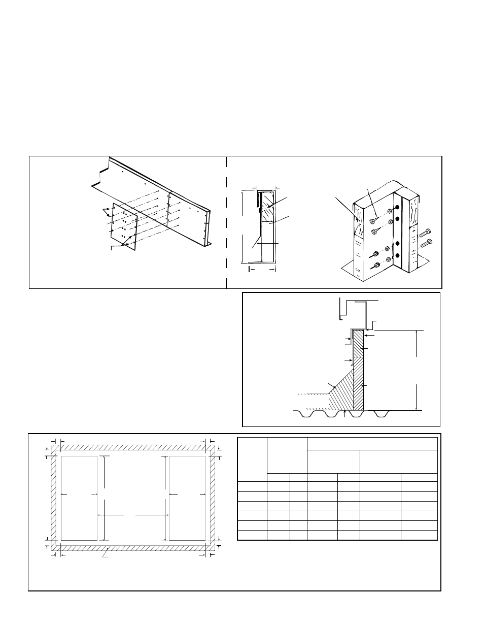
Roof Curb Assembly and Installation Instructions
Curbs are shipped unassembled. Field assembly and mounting on the roof are
the responsibility of the installer. All required hardware necessary to complete the
assembly is supplied. Before installing roof curb, verify that the size is correct for the
system being installed.
1. Position curb cross rails and curb side rails as illustrated in
FIGURE 9A. If there
are two side pieces to a side, fasten them with splice plates and hardware
as illustrated in the splicing detail drawing (
FIGURE 9B). Join the corners as
illustrated in the corner detail (
FIGURE 9B).
2. Check the assembly for squareness. Adjust the roof curb so that the diagonal
measurements are equal within a tolerance of + or - 1/8".
16
(406mm)
1-7/8(48mm)
4
(102mm)
2 x 6 Wood Nailer
1-1/2 x 3 lb
Fiberglass
Flashed by the
installer (flashing must
be under lip of curb)
Lag Screw
Cap
Screws
For top 4 holes (2 on
each side) at both
joints, from inside the
curb insert (4) 5/16
x 1 lag screws and
(4) 5/16 lockwashers.
For bottom 4 holes (2 on each
side) at both joints, from outside
of the curb insert (4) 5/16-18 x 3/4
long cap screws. Attach with 5/16
lockwashers and 5/16-18 hex nuts.
(Inside
of Curb)
Splicing
Detail
FIGURE 9B - Roof Curb
Assembly
Corner Detail
Curb Section
FIGURE 9D - Duct Opening Dimensions (inches
and mm) in relation to Roof Curb CJ Option
•
1-5/8" (41mm) is the measurement from the duct openings to the inside edge of the roof curb.
• Openings for ductwork should be 1" (25mm) larger than the duct size for installation clearance.
1-5/8
(41)
1-5/8
(41)
1-5/8(41)
1-5/8(41)
1-5/8(41)
1-5/8(41)
19-1/2
(495mm)
19-1/2
(495mm)
H
H
G
Return Air
Duct
Supply
Air Duct
Roof Curb
1-5/8
(41)
1-5/8
(41)
5.4 Mounting
Outdoor Model
(cont'd)
5.0 Suspension
and Mounting
(cont'd)
5.4.4 Mounting on a Roof Curb - Model RPBL (cont'd)
3. Level the roof curb. To ensure a good weathertight
seal between the curb cap and the roof curb, the
roof curb must be leveled in both directions with no
twist end to end. Shim level as required and secure
curb to roof deck before proceeding with flashing.
4. Install field-supplied flashing.
5. Before placing the unit into position, apply
furnished 1/4" x 1-1/4" foam sealant tape to top
surface of curb, making good butt joint at corners.
The unit must be sealed to the curb to prevent
water leakage into the curb area due to blown rain
and capillary action.
Curb Cap
Counter Flashing
(by installer)
Cant Strip
(by installer)
MUST be sealed
between curb cap
and roof curb
2 x 6
Wood
Nailer
Insulation
16
(406 mm)
Curb Height
Cabinet
Curb Cap Skirt
Weld, bolt, or lag screw curb to deck structure.
Roof Curb
Roofing Felts
(by others)
FIGURE 9C -
Detail of
Installed Curb
RPBL
Size
H
G
With Downturn
AQ5 or AQ8 (no
cooling coil)
With Cooling Coil
Cabinet with Downturn,
Options AU 11, 12, 13, 14
inches mm
inches
mm
inches
mm
400
47-5/8 1210 60-5/16
1532
127-17/32
3239
500, 600 36-5/8 930 86-5/16 2192
142-17/32
3620
700
42-1/8 1070 86-5/16
2192
148-1/32
3760
800
47-5/8 1210 86-5/16
2192
153-17/32
3900
1050
42-1/8 1070 112-5/16 2853
174-1/32
4420
1200
47-5/8 1210 112-5/16 2853
179-17/32
4560