Reznor RPBL Unit Installation Manual User Manual
Page 27
Form I-SSCBL/RPBL, P/N 149159 R7, Page 27
Top Panel (edge must be
underneath cabinet top)
Left Side
Panel
Right Side
Panel
Factory-assembled
Louver Assembly
including Moisture
Eliminating Louvers
(U.S. Patent 4,999,037)
and Screen
Bottom
Panel
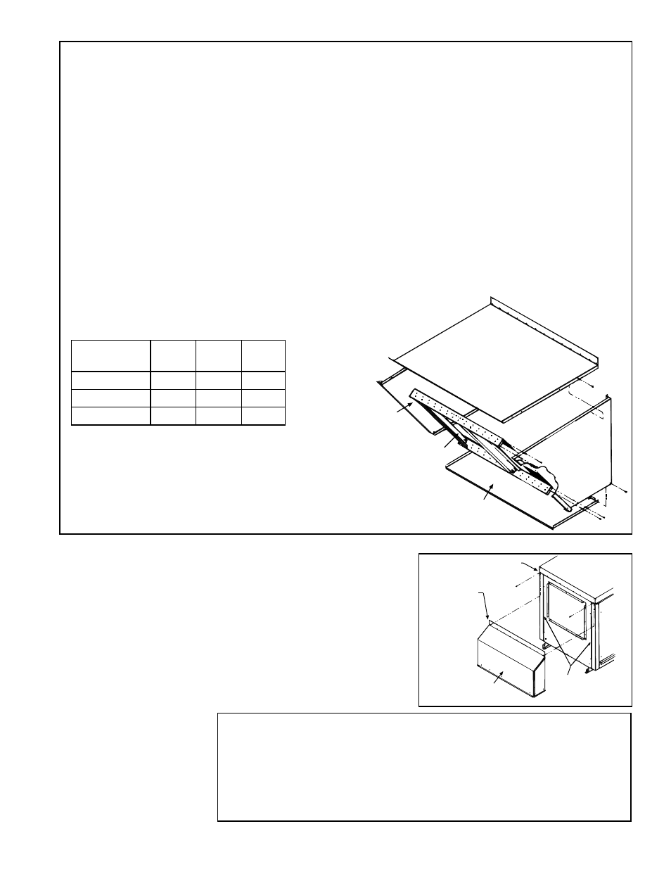
6.3.2 Screened Air
Hood for 30% Outside
Air Opening, Part
of Inlet Air Options
AR6 and AR7 - Model
RPBL
Blower
Cabinet
Remove two corner
and compete row
of screws
Slide top
flange
underneath
the cabinet
top
Vertical Slots -
Slide side flanges
into slots
30% Outside
Opening Air Hood
FIGURE 29 - Installation of Air
Hood on Cabinets with 30%
Outside Air Opening Options
FIGURE 28 - Assembly Drawing of
Option AS2 Outside Air hood
RPBL
Top
Panel
Bottom
Panel
Louver
Assy
400, 800, 1200 100232 100239 103778
500, 600
100230 100237 103776
700, 1050
100231 100238 103777
The outside air hood included in the
air inlet options that have a 30% out-
side air opening (Option AR6 or AR7)
is shipped separately for field instal-
lation. Instructions are packaged with
the air hood.
hood top panel must be between the blower cabinet top and the end panel. Reinsert all of the sheetmetal
screws.
2. Side Panels -- Slide the air hood right side panel into the groove in the blower cabinet end panel. Be sure that
the side panel is underneath and to the inside of the air hood top panel. Attach to the blower cabinet and the air
hood top using the required number of sheetmetal screws. Repeat with the left side panel.
3. Bottom Panel -- Position the air hood bottom panel so that it is to the inside of the two side panels and above
the factory-installed support angle. Attach to the side panels.
If the bottom panel does not rest tightly against the support angle, follow these instructions to adjust the position
of the support angle:
a) Slightly loosen (do not remove the screws).
b) Slide the support angle up so that it is against the bottom panel.
c) Tighten the screws.
Attach the support angle to the air hood bottom panel. The bottom panel of the air hood and the support angle
should be tight together; do not draw with the sheetmetal screws.
4. Louver Assembly -- With the intake screen toward the inside of the hood, position the pre-assembled vertical
louver assembly in the inlet opening of the air hood. Using the remaining sheetmetal screws, attach the louver
assembly to the air hood side panels using the holes provided.
Installation Instructions - 30% Outside Air Hood (FIGURE 29)
1. On the inlet air side of the blower cabinet, remove the factory installed screws
attaching the blower cabinet top.
2. Slide the air hood top flange underneath the lip of the blower cabinet top and the
sides into the vertical slots.
The air hood flange must be between the blower
cabinet top and the cabinet end panel.
3. Reinsert all of the sheetmetal screws.