0 controls (cont'd), 8 gas controls (cont'd) – Reznor RPBL Unit Installation Manual User Manual
Page 46
Form I-SSCBL/RPBL, Page 46
TABLE B - Recommended Settings for Staging Application - Options AG4, AG5, AG17, and AG19
Option
No. of
Furnaces
Ductstat Settings - Set
each Ductstat (See FIGURE 47) in furnace "order"
1st
2nd
3rd
Sequence of Staging with this setting
AG4
2
70°F
--
--
66°F Full Rate Both Furnaces ► 70°F Shutdown 1st Furnace ►
74°F Shutdown 2nd furnace
AG5
3
70°F
64°F
--
60°F Full Rate Both Furnaces ► 68°F Shutdown 2nd & 3rd
Furnace ► 74°F Shutdown 1st furnace
Options AG17, AG18, AG19, AG20 - Adjust the setpoint and the differential of the temperature selector (Johnson #A350). Adjust
the offset potentiometer on each of the stage adder modules (Johnson #S350). The settings listed below will provide the same
sequence of staging as shown above for Option AG4. Follow the manufacturer's instructions provided. IMPORTANT: Set the
temperature selector and each stage adder module to "HEAT". Follow the wiring diagram to obtain proper sequencing.
Option
No. of
Furnaces
Temperature Selector (A350)
Stage Adder (S350) Offset Settings (Refer to illustrations in
FIGURE 48)
Setpoint
Differential
AG17
2
74°F
8°F
4°F
--
--
AG19
3
74°F
10°F
6°F
6°F
--
Operation: The differential setting and offset degrees allow the controls to adapt to any adjustment in temperature selection (50-
130°F).
(A)
(B)
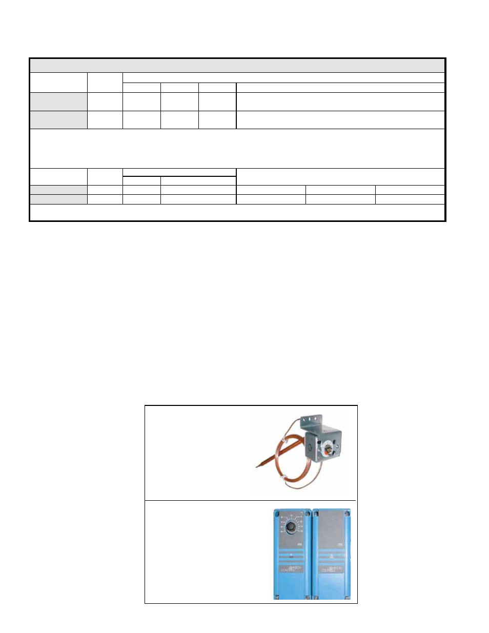
FIGURE 48 - Remote
Temperature Selector( A);
and Stage-Adder Module
(B)
for Ductstat in Makeup Air
Control Options (Options
AG 15, 17, and 19
8.0 Controls
(cont'd)
8.8 Gas Controls (cont'd)
FIGURE 47 - Ductstat
Control in Option AG3,
AG4, and AG5
Factory set as listed in
TABLES A and B.
Adjustable range 0-100°F;
markings are on the dial.
8.8.3 Optional Two-Stage Operation - Makeup Air (cont'd)
The makeup air control options with the complete two-stage ductstat (Options AG3,
AG4, AG5) installed in the heater discharge use a ductstat (See
FIGURE 47) with
an adjustable range from 0° to 100°F with a fixed differential of 2-1/2°. Due to differ-
ent CFM settings and outside air temperatures, the average downstream outlet tem-
perature may not match the ductstat setting exactly. After the installation is complete,
re-adjust the setpoint of the ductstat(s) to achieve the desired average discharge air
temperature. In general, makeup air applications are usually adjusted to discharge an
outlet air temperature between 65°F and 75°F.
Two-stage makeup air options that are controlled from a sensing probe with a remote
electronic temperature selector have a temperature operating range to 130°F. The
sensing probe and remote modules (
FIGURE 48) are shipped separately for field
installation. Follow the wiring diagram with the unit and the manufacturer's instruc-
tions for wiring and installing the remote modules.
CAUTION: Make sure heat/cool
selector switch is set on "HEAT". Depending on the staging provided, there will be
one module for selecting temperature and one to five stage-adder modules. The digital
display module is optional.
See
TABLE A, page 45, or TABLE B, above, for recommended settings and staging
sequence of all two-stage options.