0 mechanical (cont'd), 2 venting and combustion air (cont'd) – Reznor RPBL Unit Installation Manual User Manual
Page 16
Form I-SSCBL/RPBL, Page 16
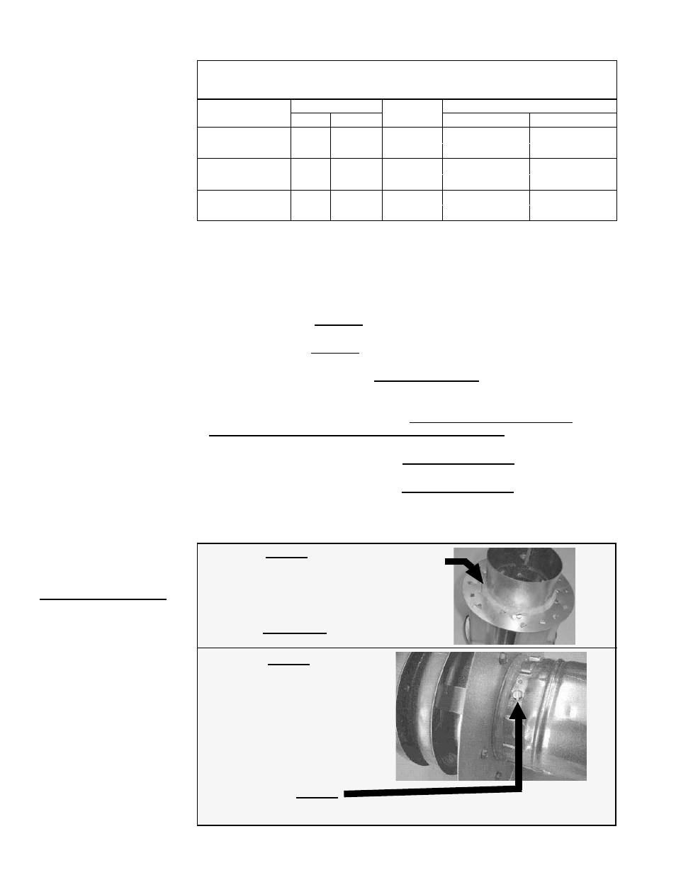
FIGURE 11 - Follow
STEPS to join Double-
Wall (Type B) Pipe and
the Vent Terminal Cap
(horizontal or vertical)
Figure 11 - STEP 1
Place a continual 3/8” bead of silicone sealant
around the circumference of the vent cap collar.
This will prevent any water inside the vent cap
from running down the double-wall pipe.
Do STEP 2 immediately following STEP 1.
Figure 11 - STEP 2
Insert the collar on the vent cap inside
the inner wall of the double-wall pipe.
Insert as far as possible. Add addi-
tional silicone sealant to fully close
any gaps between the vent cap and
the double wall pipe. This is neces-
sary to prevent water from entering
the double wall pipe.
Secure the vent cap to the double-wall pipe by drilling and inserting a 3/4” long
sheetmetal screw into the vent cap collar. Do not overtighten screw.
Figure 11 - STEP 3
(
NOTE: Pipes and vent
caps may not look exactly
as shown in the illustrations.
Instructions apply to both
horizontal and vertical vent
kits.)
6.2.1 Separated-
Combustion Model
SSCBL (cont'd)
6.0 Mechanical
(cont'd)
Maximum Pipe Length from EACH Furnace Section to a Unique
Concentric Adapter Box --
Minimum length is five feet (1.5M).
Model
SSCBL
Pipe Diameter
Maximum
Length
Equivalent Length for an Elbow
Vent
Inlet Air
90°
45°
500, 600
6"
6"
50 ft
8 ft
4 ft
(15 M)
(2.4M)
(1.2M)
400, 700, 800,
1050, 1200
6"
6"
30 ft
8 ft
4 ft
(9 M)
(2.4M)
(1.2M)
All Sizes
7"
7"
70 ft
8 ft
4 ft
(21M)
(2.4M)
(1.2M)
The outside (terminal) portion of the inlet air pipe is 8" in diameter. The 5" I.D. diameter
double-wall vent pipe runs through the 8" inlet air pipe. See
FIGURE 13, page 17. The
outdoor lengths depend on the installation. Outdoor vent length requirements are listed
in the installation instructions for the horizontal and vertical vent/combustion air kits.
5) Joints/Seals
Provide pipe as specified in Requirement No. 2 and make joints as follows:
• If using Category III vent pipe runs, follow the pipe manufacturer’s instructions
for joining and sealing Category III vent pipe sections.
• If using single-wall vent pipe runs, secure slip-fit pipe connections using
sheetmetal screws or rivets. Seal all joints with aluminum tape or silicone sealant.
• To seal joints in the single-wall combustion air pipe, secure slip fit pipe
connections using sheetmetal screws or rivets. Seal all joints with aluminum tape
or silicone sealant.
• To seal joint in the terminal section of double-wall vent pipe (allowed
ONLY ABOVE the concentric pipes on a VERTICAL vent), follow the pipe
manufacturer’s instructions for joining and sealing double-wall vent pipe sections.
• When joining the terminal section of double-wall vent pipe to the vent cap,
follow the illustrated step-by-step instructions in
FIGURE 11.
When joining the terminal section of double-wall vent pipe to a single-wall
or Category III vent pipe run, follow the illustrated step-by-step instructions in
FIGURE 12.
6.2.1.1 Specific
Venting Requirements
(cont'd) (read all before
installing)
4) Pipe Diameter and Length (cont'd)
6.2 Venting and
Combustion Air
(cont'd)