4 duct connections - sscbl and rpbl, 0 mechanical (cont'd), 3 unit inlet air (cont'd) – Reznor RPBL Unit Installation Manual User Manual
Page 38
Form I-SSCBL/RPBL, Page 38
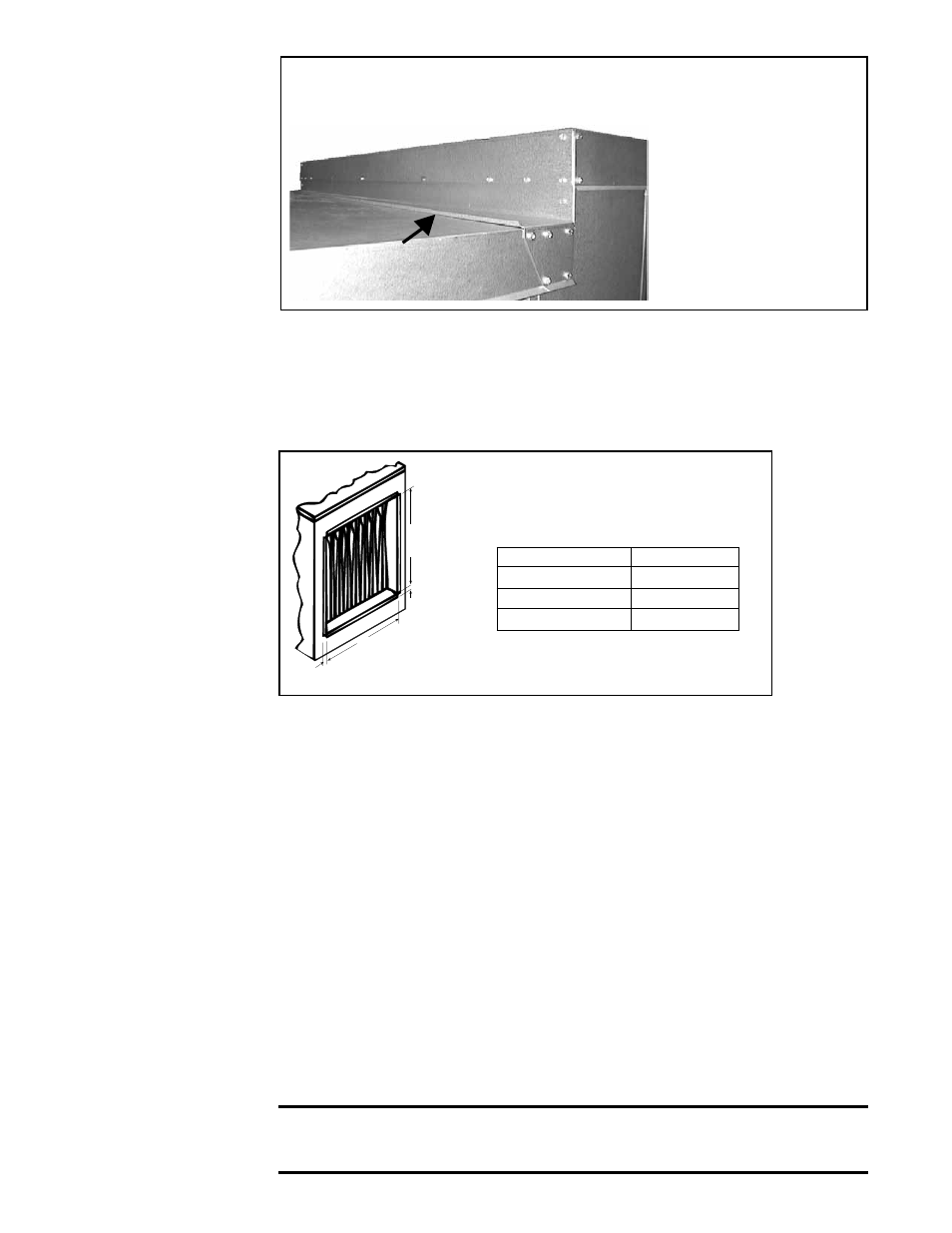
FIGURE 40K - Top Filler Panel Installed
Before the top filler
panel is attached,
remove the backing and
adhere the gasket strip
along the bottom of the
outside edge so that
any gaps between the
top filler panel and the
top panel of the furnace
section are sealed.
Filler must be
underneath
the edge of the cooling coil
cabinet top panel
10. The cooling coil cabinet is installed. Follow the instructions provided by the
cooling coil manufacturer to make cooling coil connections.
Cooling Coil
Maintenance
The cooling coil cabinet is designed with easily removable panels on both sides of the
cabinet to provide access for inspection and cleaning. Inspect the coil during routine
maintenance and whenever the filters are changed. Check the cooling coil for build up
of debris; clean as required.
6.4 Duct
Connections
- SSCBL and
RPBL
FIGURE 41 - Discharge Duct
Connection Dimensions -
inches (mm)
18
(457mm)
3/4
(19mm)
3/4
(19mm)
G
RPBL, SSCBL
G
500, 600
34-1/2 (876)
700, 1050
40 (1016)
400, 800, 1200
45-1/2 (1156)
Requirements and
Suggestions for
Connecting and
Installing Ducts
• Type of Ductwork - The type of duct installation to be used depends in part on
the type of construction of the roof (whether wood joist, steelbar joist, steel truss,
precast concrete) and the ceiling (whether hung, flush, etc.).
• Ductwork Material - Rectangular duct should be constructed of not lighter than
No. 26 U.S. gauge galvanized iron or No. 24 B & S gauge aluminum.
• Ductwork Structure - All duct sections 24 (610mm) inches or wider, and over 48
(1219mm) inches in length, should be cross broken on top and bottom and should
have standing seams or angle-iron braces. Joints should be S and drive strip, or
locked.
• Through Masonry Walls - No warm air duct should come in contact with masonry
walls. Insulate around all air duct through masonry walls with not less than 1/2" (1"
is recommended) of insulation.
• Through Unheated Space - Insulate all exposed warm air ducts passing through
an unheated space with at least 1/2" (1" is recommended) of insulation.
• Duct Supports - Suspend all ducts securely from adjacent buildings members. Do
not support ducts from unit duct connections.
• Duct Sizing - Proper sizing of the supply air ductwork is necessary to ensure a
satisfactory heating installation. The recognized authority for such information is
the Air Conditioning Contractors Association, 2800 Shirlington Road, Suite 300,
Arlington, VA 22206 (www.acca.org). A manual covering duct sizing in detail may
be purchased directly from them.
CAUTION: An external duct system static pressure not within the limits
shown on the rating plate, or improper motor pulley or belt adjustment,
may overload the motor. See Hazard Levels, page 2.
6.0 Mechanical
(cont'd)
6.3 Unit Inlet Air
(cont'd)
6.3.6 Optional Cooling
Coil Cabinet, Option
AU (cont'd)