5 blowers, belts, and drives – Reznor RPBL Unit Installation Manual User Manual
Page 39
Form I-SSCBL/RPBL, P/N 149159 R7, Page 39
Heater
Duct
Access Panel
in Duct
6
(152mm)
10 (254mm)
1
2
3
4
U Channel
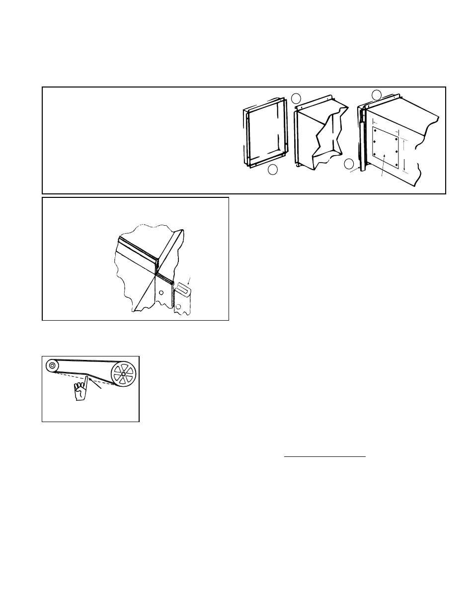
FIGURE 42 - Connecting Supply Air Duct
to the Furnace
(1) Flanges on the furnace (heat exchanger) turn
out as shown.
(2) Shape duct connection as shown -- "U" on top
and bottom; "L" on sides.
(3) Slide "U" channels over furnace top and
bottom flanges making connection.
(4) Form "U" channels to seal sides. Drill and lock
with sheetmetal screws.
• Removable Panels (See FIGURE 42.). - The ducts should have removable
access panels. These openings must be accessible when the furnace is in service
and should be a minimum of 6" x 10" (152mm x 254mm) in size so smoke or
reflected light may be observed inside the casing to indicate the presence of leaks
in the heat exchanger. Attach the covers for the openings in a manner that will
prevent leakage.
•
Horizontal Discharge Duct Length - A minimum
horizontal duct run of 24" (610mm) is
recommended
before turns or branches are made in the duct system to
reduce losses at the furnace outlet.
•
Supply Air Duct/Furnace Horizontal Connection -
The seal between the furnace and the duct must be
mechanical. Duct connection should be made with "U"
type flanges on the top and bottom of the connecting
duct. Slide the duct over the flanges of the heater giving
an airtight fit. Provide "U" type channels for the side
flanges to ensure tight joints. Use sheetmetal screws to
fasten ducts and "U" channels to the furnace flange. See
FIGURE 43.
FIGURE 43 -
Install "U"
Channel on
Sides of Duct
Connection
Furnace
Duct
U Channel
of Light
Gauge Metal
6.5 Blowers, Belts,
and Drives
3/4
(19mm)
FIGURE 44 - Check
Belt Tension
Check belt tension. Proper belt tension is important to the long life of the belt and
motor. A loose belt will cause wear and slippage. Too much tension will cause exces-
sive motor and blower bearing wear. Adjust the belt tension by turning the adjusting
screw on the motor base until the belt can be depressed 3/4" (19mm). (See
FIGURE
44.) After correct tension is achieved, re-tighten the locknut on the adjustment screw.
Be sure that the belt is aligned in the pulleys.
Adjusting Blower Speed
The system is set at the factory for the RPM required to meet the CFM and external
static pressure specified on the order. If estimated external static pressure is incorrect,
or changes were made to the duct system, the blower RPM may have to be adjusted.
Motors are equipped with adjustable pitch pulleys which permit adjustment of blower
speed.
To make adjustments to units with less than a 5HP motor, follow these instruc-
tions.
1. Turn off the gas and the electric power.
2. Loosen belt tension and remove the belt.
3. Loosen the set screw on the side of the pulley away from the motor.
4. To increase the blower speed, decreasing outlet temperature, turn the
adjustable half of the pulley inward.
To decrease the blower speed, increasing
the outlet temperature, turn the adjustable half of the pulley outward. One turn of
the pulley will change the speed 8-10%.
5. Tighten the set screw on the flat portion of the pulley shaft.
6. Replace the belt and adjust the belt tension. Adjust tension by turning the
adjusting screw on the motor base until the belt can be depressed 3/4". (See
FIGURE 44.) Re-tighten the lock nut on the adjusting screw. Be sure that the belts
are aligned in the pulley grooves properly and are not angled from pulley to pulley.