0 mechanical (cont'd), 1 gas piping and pressures (cont'd), Sizing gas supply lines – Reznor RPBL Unit Installation Manual User Manual
Page 14
Form I-SSCBL/RPBL, Page 14
Sizing Gas Supply Lines
Manifold or Orifice
(Valve Outlet) Pressure
Settings
6.0 Mechanical
(cont'd)
6.1 Gas Piping
and Pressures
(cont'd)
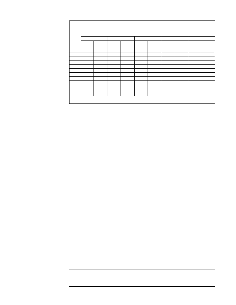
Capacity of Piping - Cubic Feet per Hour based on 0.3" w.c. Pressure Drop
Specific Gravity for Natural Gas -- 0.6 (Natural Gas -- 1000 BTU/Cubic Ft)
Specific Gravity for Propane Gas -- 1.6 (Propane Gas -- 2550 BTU/Cubic Ft)
Length
of Pipe
Diameter of Pipe
1"
1-1/4"
1-1/2"
2"
2-1/2"
Natural Propane Natural Propane Natural Propane Natural Propane Natural Propane
20'
350
214
730
445
1100
671
2100
1281
3300
2013
30'
285
174
590
360
890
543
1650
1007
2700
1647
40'
245
149
500
305
760
464
1450
885
2300
1403
50'
215
131
440
268
670
409
1270
775
2000
1220
60'
195
119
400
244
610
372
1105
674
1850
1129
70'
180
110
370
226
560
342
1050
641
1700
1037
80'
170
104
350
214
530
323
990
604
1600
976
90'
160
98
320
195
490
299
930
567
1500
915
100'
150
92
305
186
460
281
870
531
1400
854
125'
130
79
275
168
410
250
780
476
1250
763
150'
120
73
250
153
380
232
710
433
1130
689
175'
110
67
225
137
350
214
650
397
1050
641
200'
100
61
210
128
320
195
610
372
980
598
Note: When sizing supply lines, consider possibilities of future expansion and increased requirements.
Refer to National Fuel Gas Code for additional information on line sizing.
Measuring manifold gas pressure cannot be done until the heater is in operation. It is
included in the steps of the "Check-Test-Start" procedure in Paragraph 9.0. The follow-
ing warnings and instructions apply.
For Natural Gas: When the heater leaves the factory, the combination valve is set so
that the outlet gas pressure of a single-stage valve or high fire of a two-stage valve is
regulated to 3.5" w.c. Low fire on a two-stage valve is set to 1.8" w.c. Inlet supply pres-
sure to the valve must be a minimum of 5" w.c. or
as noted on the rating plate and a
maximum of 14" w.c.
NOTE: Always check the rating plate for minimum gas sup-
ply pressure. Minimum supply pressure requirements vary based on size of burner
and the gas control option. Most units require a minimum of 5" w.c. of natural gas as
stated above, but larger sizes with electronic modulation require a minimum of 6" w.c.
natural gas supply pressure.
For Propane: When the heater leaves the factory, the combination valve is set so that
the outlet gas pressure of a single-stage valve or high fire of a two-stage valve is 10"
w.c. Low fire on a two-stage valve is set to 5" w.c. Inlet pressure to the valve must be
a minimum of 11" w.c. and a maximum of 14" w.c.
Before attempting to measure or adjust manifold gas pressure, the inlet (supply) pres-
sure must be within the specified range for the gas being used both when the heater is
in operation and on standby. Incorrect inlet pressure could cause excessive manifold
gas pressure immediately or at some future time.
Instructions to Check Valve Outlet (Manifold) Pressure:
1) With the manual valve (on the combination valve) positioned to prevent flow to the
main burners, connect a manometer to the 1/8" pipe outlet pressure tap in the valve.
NOTE: A manometer (fluid-filled gauge) is recommended rather than a spring type
gauge due to the difficulty of maintaining calibration of a spring type gauge.
2) Open the valve and operate the heater. Measure the gas pressure to the manifold.
To measure the low stage pressure on units equipped with a two-stage valve, discon-
nect the wire from the "HI" terminal on the valve. (Be sure to reconnect the wire.)
Normally adjustments should not be necessary to the factory preset regulator. If adjust-
ment is necessary, set pressure to correct settings by turning the regulator screw IN
(clockwise) to increase pressure. Turn regulator screw OUT (counterclockwise) to
decrease pressure. Consult the valve manufacturer's literature provided with the fur-
nace for more detailed information.
CAUTION: DO NOT bottom out the gas valve regulator adjusting
screw. This can result in unregulated manifold pressure causing
overfire and heat exchanger failure.