Reznor RPBL Unit Installation Manual User Manual
Page 17
Form I-SSCBL/RPBL, P/N 149159 R7, Page 17
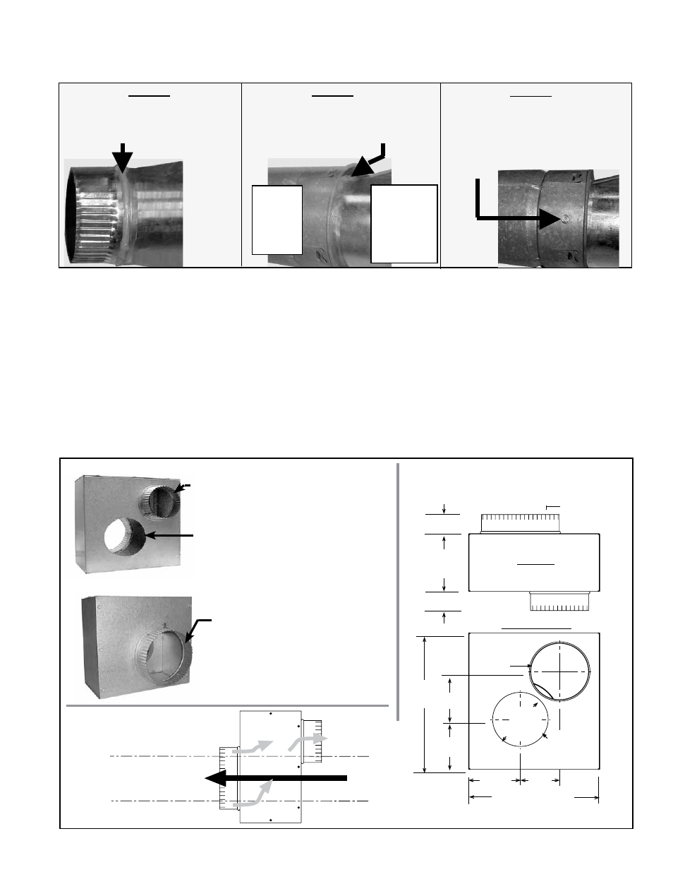
FIGURE 12 - Follow STEPS to join the Double-Wall (Type B) Pipe to the Taper-type Reducer that
Joins it to the Single-Wall or Category III Vent Run
Figure 12 - STEP 1
On the taper-type reducer, place a
continual 1/4” bead of silicone seal-
ant around the circumference.
Figure 12 - STEP 2
Insert the collar of the reducer into the
inner pipe of the double-wall pipe until
the bead of sealant contacts the inner
pipe creating a sealed joint.
Figure 12 - STEP 3
Spaced equally around the double-
wall pipe, drill three small holes
below the sealant ring. Insert 3/4 inch
long sheetmetal screws to secure the
joint. Do not overtighten screws.
Make this connection a maximum of 6" (152mm) from the concentric adapter box.
5" I.D.
Double-
Wall
Pipe
6" to 5"
or 7" to
5" Taper-
Type
Reducer
Do STEP
2 imme-
diately
following
STEP 1.
6) Support
Support horizontal runs every six feet (1.8M). Support vertical runs of type "B" double-wall or Category III vent pipe
in accordance with the requirements of the pipe manufacturer. Support single-wall vertical pipe in accordance with
accepted industry practices. Do not rely on the heater or the adapter box for support of either horizontal or vertical pipes.
Use non-combustible supports on vent pipe.
7) Clearance
Do not enclose the vent pipe or place pipe closer than 6" (152mm) to combustible material.
All separated combustion installations
require a concentric adapter box as illustrated in FIGURE 13. The concentric
adapter box is included in the vent/combustion air kit. Installation instructions depend on whether the vent system is
horizontal (Option CC6) or vertical (Option CC2).
8) Concentric Adapter Box
FIGURE 13 - A Concentric Adapter Box is Required for EACH Furnace Section of a Model SSCBL
Installation
View of Heater Connection Side
View of Vent Terminal Connection Side
P/N 205885, Concentric Adapter Box
Top View
Heater Side View
6 Collar for
Combustion
Air Pipe
Opening for
vent pipe to
pass through
the box
2 (51mm)
2 (51mm)
6-1/32
(153mm)
8 dia Collar
for Combustion
Air Pipe
14-1/4
(362mm)
5
(127mm)
5-7/32
(133mm)
5-21/32
(144mm)
diameter
5-9/32
(134mm)
4
(102mm)
13-3/8 (340mm)
Collar for connecting indoor
portion of the combustion air pipe
Opening for double-wall vent
pipe to pass through the box.
End View
showing
Airflow
Gray Arrows
show Flow of
Combustion Air
Vent (exhaust gas) flows through
field-supplied double-wall pipe
that extends straight through
the concentric adapter box.
Collar for attaching outside
concentric portion of the 8"
combustion air pipe
Concentric
Adapter Box
Airflow
Dimensions
If cross supports are used under
the 4x4 rails, do not enclose the
area under the furnace; leave
open space for ventilation.