0 controls, 1 control locations, 2 fan control – Reznor RPBL Unit Installation Manual User Manual
Page 43
Form I-SSCBL/RPBL, P/N 149159 R7, Page 43
Optional Downturn
Plenum Cabinet
(Option AQ5 or AQ8)
27 30 31 32 33 34 35 36 37 38 39 40
41 1 2 3
4 5 6
26 29 25 28 24 23 22 21 20 19 18 17 16 15 14 13 12
11B
11A
10 9 8
7
NOTE: Illustration
of cabinet is not
entirely accurate
for these models.
Models SSCBL and
RPBL have one,
two, or three furnace
sections.
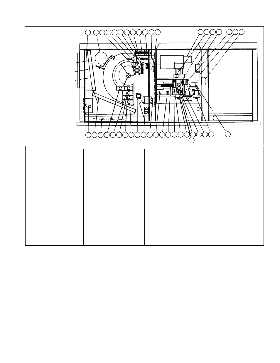
FIGURE 46 -
Locations
of Standard
and Optional
Controls
8.0 Controls
8.1 Control Locations
1) Optional Auto Reset
Freezestat
2) Combustion Air Pressure
Switch
3) Optional Discharge Air
Firestat
4) Ignition Controller
5) Optional Maxitrol
Discharge Air Sensor
(Opt AG8 or AG9)
6) Optional Two-Stage
Controller (Opt AG3) or
Maxitrol Amplifier (Opt
AG7, AG8 or AG9)
7) Optional Main Low Gas
Pressure Switch
8) Optional Pilot High Gas
Pressure Switch
9) Optional Main High Gas
Pressure Switch
10) Time Delay Relay
(power-vented)
11A) Limit Control (disc type
limit control)
11B) Limit Control (capillary
type limit control)
12) Fan Control
13) Optional Freezestat Time
Delay Relay
14) Line Voltage Terminal
Block
15) Low Voltage Terminal
Block
16) Freezestat Relay
17) Optional Dirty Filter
Pressure Switch
18) Line Voltage Connection
(field)
19) Opt Convenience Outlet
and Outlet Transformer
20) Blower Motor Contactor or
Starter
21) Optional High Ambient
Limit Control and/or
Optional AG41 or 42 Heat
Stage Controls (2 or 4)
22) Optional Outside Air or
Return Air Controller
23) Optional Mixed Air
Controller
24) Optional Potentiometer
25) Optional Return Air
Dampers
26) Optional Two Position or
Modulating Damper Motor
27) Optional Outside Air
Damper
28) Optional Potentiometer
29) Optional Filters
30) Blower Motor
31) Optional Control Relays
(as required, 8 maximum)
32) Auto Reset Reverse Flow
Limit
33) Optional Return Air
Firestat
34) Low Voltage Terminal
Strip
35) Line Voltage Terminal
Strip
36) Control Transformer
37) Control Transformer (as
required)
38) Optional Damper Motor
Transformer
39) Low Voltage Connection
(field)
40) Optional Air Proving
Switch
41) Venter Assembly
8.2 Fan Control
1. A fan control provides for the following control of the blower.
(a) After the gas valve opens, there is a time delay of blower operation to prevent
the discharge of cold air.
(b) Blower operation continues after the thermostat is satisfied as determined by
the fan time delay.
2. To be sure that the blower can continue to operate, the power supply to the
furnace
MUST NOT be interrupted except when servicing the unit.
3. If the customer wants the furnace off at night, the gas valve circuit SHOULD
BE OPENED by a single pole switch wired in series with the thermostat. Some
thermostats are provided with this feature. Multiple units controlled from a single
thermostat are shut off in the same manner. For proper operation, be sure the fan
control wiring is observed
Refer to the wiring diagram furnished with the furnace. For location, See
FIGURE 46
Item 12.
Service NOTE: To replace a fan control on units manufactured prior to 11/04, a
replacement kit is required. Order
P/N 209184.