2 optional two- stage operation - heating only, 3 optional two- stage operation - makeup air – Reznor RPBL Unit Installation Manual User Manual
Page 45
Form I-SSCBL/RPBL, P/N 149159 R7, Page 45
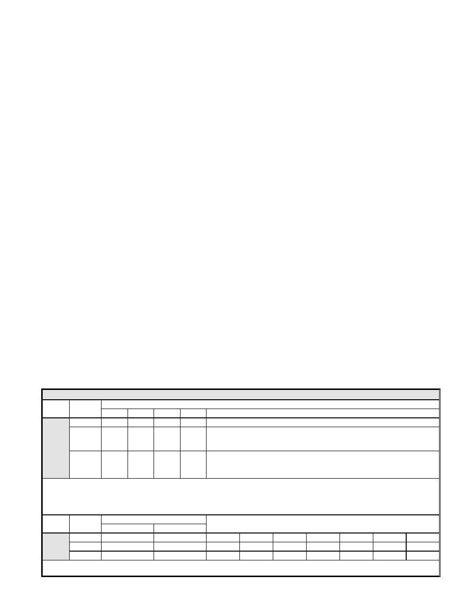
TABLE A - Recommended Settings for Staging Application - Options AG3, AG15
Option
No. of
Furnaces
Ductstat Settings - Set
each ductstat control (See FIGURE 47) in furnace "order"
1st
2nd
3rd
4th
Sequence of Staging with these settings
AG3
1
70°F
--
--
--
66°F High Stage ► 70°F Low Stage ► 74°F Shutdown
2
70°F
64°F
--
--
60°F High Stage Both Furnaces ► 64°F Low Stage 2nd Furnace ► 68°F
Shutdown 2nd furnace ► 70°F Low Stage 1st furnace ► 74°F Shutdown
1st furnace
3
70°F
66°F
62°F
--
58°F High Stage All Furnaces ► 62°F Low Stage 3rd Furnace ► 66°F
Shutdown 3rd Furnace; Low Stage 2nd Furnace ► 70°F Shutdown 2nd
furnace; Low Stage 1st Furnace ► 74°F Shutdown 1st Furnace
Option AG15 - Adjust the setpoint and the differential of the temperature selector (Johnson #A350). Adjust the offset
potentiometer on each of the stage adder modules (Johnson #S350). The settings listed below will provide the same sequence
of staging as shown above for Option AG3. Follow the manufacturer's instructions provided. IMPORTANT: Set the temperature
selector and each stage adder module to "HEAT". Follow the wiring diagram to obtain proper sequencing.
Option
No. of
Furnaces
Temperature Selector (A350)
Stage Adder (S350) Offset Settings (Refer to
FIGURE 48)
Setpoint
Differential
AG15
1
74°F
8°F
4°F
--
--
--
--
--
--
2
74°F
14°F
10°F
6°F
4°F
--
--
--
--
3
74°F
16°F
10°F
8°F
8°F
4°F
4°F
--
--
Operation: The differential setting and offset degrees allow the controls to adapt to any adjustment in temperature selection (50-
130°F).
All furnaces are standardly equipped with a 24-volt combination valve which includes
the automatic electric on-off valve controlled by the room thermostat, the pressure
regulator, the safety pilot valve, and the manual shutoff valve. The standard gas valve
allows for single-stage control from a single-stage, 24-volt thermostat.
8.8.2 Optional Two-
Stage Operation -
Heating Only
The standard combination control valve is replaced with a two-stage combination gas
control valve providing for low fire or high fire operation controlled by a two-stage
thermostat. First stage (low fire) is factory set (not field adjustable). Both high and low
stages are controlled by a Servo regulator, maintaining constant gas input under wide
variations in gas supply pressure. See instructions packed with the unit for specific gas
valve specifications, wiring, and operating instructions.
8.8.3 Optional Two-
Stage Operation -
Makeup Air
On systems with more than one furnace section, there are two methods of achieving
multiple-stage makeup air operation. In addition, for each of these methods, there are
two types of control mechanisms. Consult the wiring diagram on the furnace to identify
the optional control system (Option AG 3, 15, 4, 5, 17, 18, 19, or 20).
The first method, identified by Options AG3 or AG15, is comparable to the two-stage
heating units. Instead of control from a two-stage room thermostat, the discharge air
temperature is monitored and the two-stage gas valve is controlled by a two-stage
ductstat. When the discharge air temperature drops to the setpoint, low fire is ener-
gized. If low fire cannot satisfy the ductstat setting, high fire is energized. Since the
packaged systems may include two or three furnace sections, and each section is
equipped with a two-stage gas valve, the operation stages increase with the number of
furnace sections. Set the ductstats as indicated in
TABLE A, below.
The second method of multiple-stage makeup air operation is applicable only to
systems that include two or three furnace sections. On systems with two furnaces,
this optional control system is identified as
Option AG4, AG17, or AG18. On pack-
aged systems with three furnace sections, this optional control method is identified
as
Option AG5, AG19, or AG20. Each furnace in the package is equipped with a
single-stage gas valve. The single-stage gas valves are staged by two-stage ductstats.
The furnaces are staged in sequence. This concept will achieve two-stage control on
packaged systems with two furnaces and three-stage control on systems with three
furnaces. Set the ductstats as indicated in
TABLE B, page 46.
The two types of ductstat control mechanisms used in these multiple-stage systems
are
either --
(1) the complete ductstat (including the sensor and temperature selector; see FIGURE
47) is installed in the furnace discharge (Option AG3, AG4, and AG5) or
(2) a sensing probe only is installed in the heater discharge (See FIGURE 49.) with the
sensing probe electrically connected to a remote electronic temperature selector
(
FIGURE 48).