0 mechanical (cont'd), 5 blowers, belts, and drives (cont'd) – Reznor RPBL Unit Installation Manual User Manual
Page 40
Form I-SSCBL/RPBL, Page 40
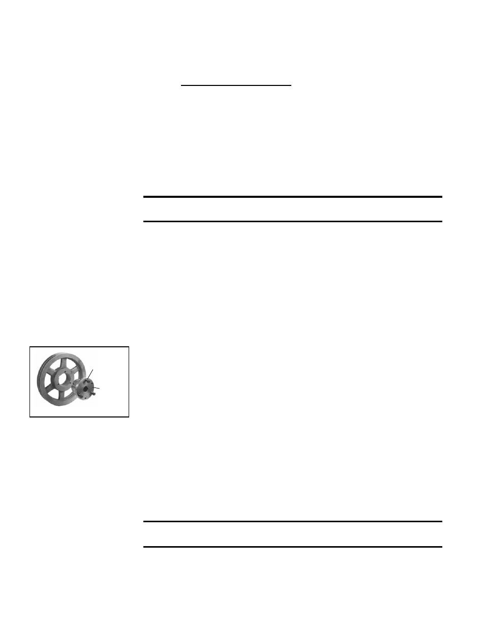
FIGURE 45 - Split Taper
Bushing
Cap
Screws
Push-
Off
Holes
6.5 Blowers, Belts,
and Drives
(cont'd)
6.0 Mechanical
(cont'd)
Adjusting Blower
Speed (cont'd)
7. Turn on the electric and the gas. Light the heater following the instructions on the
lighting instruction plate.
8. Check the motor amps with an amp meter. The maximum motor amp rating on the
motor nameplate must not be exceeded.
9. When installation is complete, check for proper operation.
For units with a 5 HP and larger motor, follow these instructions for adjusting
RPM:
1. Turn off the gas and the electric power.
2. Slack off all belt tension by moving motor towards driven shaft until belts are free
of grooves. For easiest adjustment, remove the belts from the grooves.
3. On the outer locking ring, locate the two locking screws that are directly across
from each other. Loosen these two screws, but do not remove them. Do not
loosen any other screws.
4. Adjust sheave to desired pitch diameter by turning the outer locking ring. One
complete turn of the outer locking ring will result in .233" change in pitch diameter.
To
decrease blower speed, increase diameter; to increase blower speed,
decrease diameter.
CAUTION: Sheaves should not be adjusted in either direction to the
point where movable and stationary flanges are in contact.
5. After completing adjustment, tighten both locking screws in the outer locking ring
(loosened in Step 2.).
6. Replace belts and move motor away from the driven shaft to apply sufficient belt
tension to prevent slippage. (See
FIGURE 44.) Proper belt tension is important to
the long life of the belt and motor. A loose belt will cause wear and slippage. Too
much tension will cause excessive motor and blower bearing wear. Be sure that
the belts are aligned in the pulley grooves and are not angled from pulley to pulley.
7. Check motor amps with an amp meter. The maximum motor amp rating on the
nameplate must not be exceeded.
8. When installation is complete, check for proper operation.
Blower Pulley - Some blower pulleys require the use of a split taper bushing in the
blower pulley. These split taper bushings must be loosened in order to remove the pul-
ley. Follow these instructions to loosen the bushing:
a) Notice that there are three cap screws in the bushing and two holes without
screws, called push-off holes. (See
FIGURE 45.)
b) Remove the three cap screws.
c) Put two of the cap screws into the two push-off holes. Tighten these two screws
evenly until the pulley is loosened.
d) Pulley may now be removed from the shaft.
Blower Bearings - The blower bearings on systems with less than a 10 HP motor
(standard blower) are permanently lubricated cartridge ball bearings and do not require
greasing.
The blower bearings on systems equipped with a 10-20 HP motor are pillow block ball
bearings and are equipped with a grease fitting. These bearings should be lubricated
twice a year with a high temperature, moisture-resistant grease (Type NLGI-1 or -2
standard grease is recommended). Be sure to clean the grease fitting before adding
grease. Add grease with a handgun until a slight bead of grease forms at the seal.
Be careful not to unseat the seal by over lubricating.
NOTE: If unusual environmental
conditions exist (temperatures below 32°F or above 200°F; moisture; or contaminants)
or if unit is in continuous operation, more frequent service is required.
CAUTION: If the blower is unused for more than three months, bearings
with a grease fitting should be purged with new grease pri
or to startup.
Blower Rotation - Each blower housing is marked for proper rotation. Rotation may
be changed on single-phase motors by re-wiring in the motor terminal box. Three-
phase motors may be reversed by interchanging two wires on the 3-phase supply
connections.